HYBRID / BATTERY CONTROL 8ZR-FXE FRAME WIRE REMOVAL
CAUTION / NOTICE / HINT
The necessary procedures (adjustment, calibration, initialization or registration) that must be performed after parts are removed and installed, or replaced during floor under wire removal/installation are shown below.
| Replaced Part or Performed Procedure | Necessary Procedure | Effect/Inoperative Function when Necessary Procedure not Performed | Link |
|---|---|---|---|
| Front wheel alignment adjustment | 1.
Perform "Reset Memory" 2.
Perform "Calibration" |
·
DTCs are stored ·
ABS warning light illuminates ·
Brake system warning light (yellow indicator) illuminates ·
Slip indicator light illuminates ·
Electronically controlled brake system disabled or malfunctions |
( 202304,999999,_54,_080770,_0392591,RM100000002B671,) 202304,999999,_54,_080770,_0392591,RM100000002B671,)
|
- CAUTION:
- ·
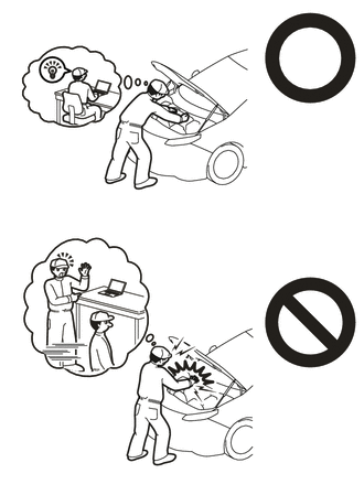
Orange wire harnesses and connectors indicate high-voltage circuits. To prevent electric shock, always follow the procedure described in the repair manual.
·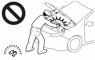
To prevent electric shock, wear insulated gloves when working on wire harnesses and components of the high voltage system.
- NOTICE:
-
After turning the power switch off, waiting time may be required before disconnecting the cable from the negative (-) auxiliary battery terminal. Therefore, make sure to read the disconnecting the cable from the negative (-) auxiliary battery terminal notices before proceeding with work.
- HINT:
-
When the cable is disconnected / reconnected to the auxiliary battery terminal, systems temporarily stop operating. However, each system has a function that completes learning the first time the system is used.
Items for which learning is completed by driving the vehicle Effect/Inoperative Function when Necessary Procedure not Performed Necessary Procedure Link Front Camera System Drive the vehicle straight ahead at 15 km/h (9 mph) or more for 1 seconds or more. ( 202304,999999,_95,_139716,_0584193,RM1000000029F4C,)
PROCEDURE

 1. PRECAUTION
G3834
2.REMOVE SERVICE PLUG GRIP
3.REMOVE CONNECTOR COVER ASSEMBLY
4.CHECK TERMINAL VOLTAGE
5.TEMPORARILY INSTALL CONNECTOR COVER ASSEMBLY
821H1
6.DISCONNECT FLOOR UNDER WIRE
73350C
7.DISCONNECT REAR CENTER SEAT OUTER BELT ASSEMBLY
for Fold Down Seat Type:
8.REMOVE REAR SEAT CUSHION ASSEMBLY
for Fold Down Seat Type:
72693
9.REMOVE REAR SEAT CUSHION LOCK HOOK
for Fold Down Seat Type:
67918A
10.REMOVE REAR DOOR SCUFF PLATE LH
76974F
11.REMOVE REAR UNDER SIDE COVER LH
67917A
12.REMOVE REAR DOOR SCUFF PLATE RH
- HINT:
-
Use the same procedure as for the LH side.
76973F
13.REMOVE REAR UNDER SIDE COVER RH
- HINT:
-
Use the same procedure as for the LH side.
76971G
14.REMOVE REAR UNDER COVER
71033
15.REMOVE REAR SEAT CUSHION LEG SUB-ASSEMBLY
G92N4A
16.REMOVE NO. 1 HV BATTERY COVER PANEL RH
821H1
17.DISCONNECT FLOOR UNDER WIRE
57627G
18.REMOVE REAR FLOOR SIDE MEMBER COVER RH
58165C
19.REMOVE FRONT FLOOR COVER RH
- HINT:
-
Perform the same procedure as for the front floor cover LH.
51201
20.REMOVE FRONT SUSPENSION CROSSMEMBER SUB-ASSEMBLY
821H1
21.REMOVE FLOOR UNDER WIRE
- CAUTION:
-
Be sure to wear insulated gloves.
- NOTICE:
-
Insulate the disconnected connectors with insulating tape.
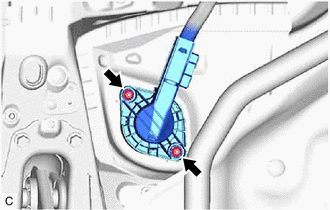
Remove the 2 nuts.
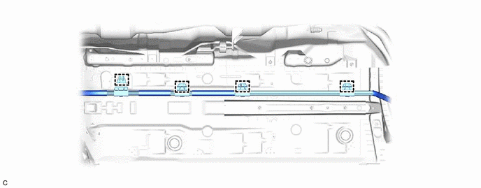
Disengage the 4 clamps.
- NOTICE:
-
If the clamps are removed forcibly, the stud bolts may be damaged.
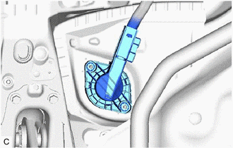
Disengage the grommet and pull out the floor under wire from the floor panel hole.
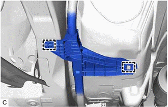
Disengage the 2 clamps.
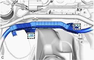
Disengage the 2 clamps to remove the floor under wire.