HEATING / AIR CONDITIONING AIR CONDITIONING SYSTEM(for HV Model (8ZR-FXE)) B13AB7F Front Control Rear Air Outlet Damper Control Servo Motor Actuator Stuck Off
DESCRIPTION
The air conditioning amplifier assembly controls the opening angle and rotates the motor of the No. 2 air conditioning radiator damper servo sub-assembly in accordance with the calculated target opening angle.
Also, the air conditioning amplifier assembly monitors the opening angle of the No. 2 air conditioning radiator damper servo sub-assembly, and when the target opening angle is not reached, this DTC is stored.
| DTC No. | Detection Item | DTC Detection Condition | Trouble Area | Memory |
|---|---|---|---|---|
| B13AB7F | Front Control Rear Air Outlet Damper Control Servo Motor Actuator Stuck Off | When it is detected that the accumulated drive time when being driven in one direction becomes 30 seconds or more | ·
No. 2 air conditioning radiator damper servo sub-assembly ·
Air conditioning harness assembly ·
Air conditioning amplifier assembly ·
Air conditioning radiator assembly |
Memorized |
WIRING DIAGRAM
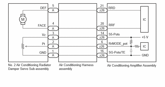
PROCEDURE
Check for DTCs.
- Body Electrical > Air Conditioner > Trouble Codes
- 50001 450
- HINT:
-
Check whether a DTC is output for another servo motor.
- Result:
Result Proceed to Only B13AB7F is output A B14037F, B14067F or B143B7F are output B
A
B
Check that the No. 2 air conditioning radiator damper servo sub-assembly is installed correctly.
- OK:
The No. 2 air conditioning radiator damper servo sub-assembly is installed correctly.
- Result:
Proceed to OK NG
OK
NG
Check for a wire harness caught between the links of the motors and dampers.
- OK:
No wire harnesses are caught between the links of the motors and dampers.
- Result:
Proceed to OK NG
OK
NG
Using the GTS, perform the following Active Test and read the Data List value.
- Body Electrical > Air Conditioner > Active Test
-
Tester Display Measurement Item Control Range Diagnostic Note Fr Ctrl Rr Air Outlet Damper Ctrl Motor (Potentio) This test activates the Fr Ctrl Rr air outlet damper ctrl motor (potentio).
(No. 2 air conditioning radiator damper servo sub-assembly)0 %: Min
100 %: MaxOperate with the ignition switch ON.
- Body Electrical > Air Conditioner > Data List
-
Tester Display Measurement Item Range Normal Condition Diagnostic Note Front Ctrl Rr Air Outlet Damper Control Motor Target Opening (Potentio) No. 2 air conditioning radiator damper servo sub-assembly target opening (potentio) 0 to 100.00 % ·FACE: 0 %
·B/L: 18 %
·FOOT-A, FOOT-O: 46.5 %
·F/D, FOOT-D, FOOT-R: 63.5 %
·FOOT-F: 69 %
·DEF-FOOT: 81 %
·DEF/S-FLOW: 100 %
No. 2 air conditioning radiator damper servo sub-assembly circuit malfunction Front Ctrl Rr Air Outlet Damper Control Motor Actual Opening (Potentio) No. 2 air conditioning radiator damper servo sub-assembly actual opening (potentio) -327.68 to 327.68 % ·FACE: 0 %
·B/L: 18 %
·FOOT-A, FOOT-O: 46.5 %
·F/D, FOOT-D, FOOT-R: 63.5 %
·FOOT-F: 69 %
·DEF-FOOT: 81 %
·DEF/S-FLOW: 100 %
No. 2 air conditioning radiator damper servo sub-assembly circuit malfunction
- Body Electrical > Air Conditioner > Active Test
-
Active Test Display Fr Ctrl Rr Air Outlet Damper Ctrl Motor (Potentio) -
Data List Display Front Ctrl Rr Air Outlet Damper Control Motor Target Opening (Potentio) Front Ctrl Rr Air Outlet Damper Control Motor Actual Opening (Potentio) - 50004 450 87 456,457
- OK:
The value of the Data List changes in accordance with the changes of the Active Test and the actual value matches the target opening angle of the Data List.
- Result:
Result Proceed to OK A NG (The value of the Data List changes in accordance with the changes of the Active Test, but the actual value does not match the target opening angle of the Data List.) B NG (The value of the Data List does not change in accordance with the changes of the Active Test) C
A
B
C
Disconnect the A No. 2 air conditioning radiator damper servo sub-assembly connector.
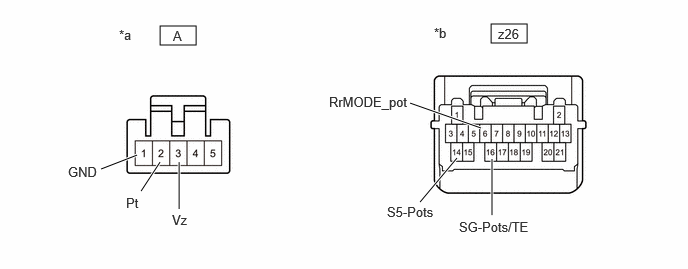
| *a | Front view of air conditioning harness assembly connector
(to No. 2 Air Conditioning Radiator Damper Servo Sub-assembly) |
*b | Front view of air conditioning harness assembly connector
(to Air Conditioning Amplifier Assembly) |
Disconnect the z26 air conditioning amplifier assembly connector.
Measure the resistance according to the value(s) in the table below.
- Standard Resistance:
Tester Connection Condition Specified Condition A-3 (Vz) - z26-14 (S5-Pots) Always Below 1 Ω A-2 (Pt) - z26-6 (RrMODE_pot) Always Below 1 Ω A-1 (GND) - z26-16 (SG-Pots/TE) Always Below 1 Ω A-3 (Vz) or z26-14 (S5-Pots) - Other terminals and body ground Always 10 kΩ or higher A-2 (Pt) or z26-6 (RrMODE_pot) - Other terminals and body ground Always 10 kΩ or higher A-1 (GND) or z26-16 (SG-Pots/TE) - Other terminals and body ground Always 10 kΩ or higher
- Result:
Proceed to OK NG
OK
NG
Remove the No. 2 air conditioning radiator damper servo sub-assembly.
Operate the damper by hand.
- OK:
The damper lightly operates by hand.
- Result:
Proceed to OK NG
OK
NG
Disconnect the A No. 2 air conditioning radiator damper servo sub-assembly connector.
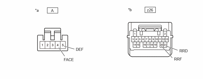
| *a | Front view of air conditioning harness assembly connector
(to No. 2 Air Conditioning Radiator Damper Servo Sub-assembly) |
*b | Front view of air conditioning harness assembly connector
(to Air Conditioning Amplifier Assembly) |
Disconnect the z26 air conditioning amplifier assembly connector.
Measure the resistance according to the value(s) in the table below.
- Standard Resistance:
Tester Connection Condition Specified Condition A-4 (FACE) - z26-20 (RRF) Always Below 1 Ω A-5 (DEF) - z26-21 (RRD) Always Below 1 Ω A-4 (FACE) or z26-20 (RRF) - Other terminals and body ground Always 10 kΩ or higher A-5 (DEF) or z26-21 (RRD) - Other terminals and body ground Always 10 kΩ or higher
- Result:
Proceed to OK NG
OK
NG
- Result:
Proceed to OK NG
OK
NG
Check for DTCs.
- Body Electrical > Air Conditioner > Trouble Codes
- 50001 450
- HINT:
-
Check whether an evaporator temp. sensor (No. 1 cooler thermistor) DTC is output.
- Result:
Result Proceed to P053511 and P053515 are not output A P053511 is output B P053515 is output C
A
B
C
Disconnect the A No. 2 air conditioning radiator damper servo sub-assembly connector.
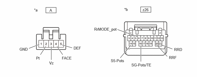
| *a | Front view of air conditioning harness assembly connector
(to No. 2 Air Conditioning Radiator Damper Servo Sub-assembly) |
*b | Front view of air conditioning harness assembly connector
(to Air Conditioning Amplifier Assembly) |
Disconnect the z26 air conditioning amplifier assembly connector.
Measure the resistance according to the value(s) in the table below.
- Standard Resistance:
Tester Connection Condition Specified Condition A-4 (FACE) - z26-20 (RRF) Always Below 1 Ω A-5 (DEF) - z26-21 (RRD) Always Below 1 Ω A-3 (Vz) - z26-14 (S5-Pots) Always Below 1 Ω A-2 (Pt) - z26-6 (RrMODE_pot) Always Below 1 Ω A-1 (GND) - z26-16 (SG-Pots/TE) Always Below 1 Ω A-4 (FACE) or z26-20 (RRF) - Other terminals and body ground Always 10 kΩ or higher A-5 (DEF) or z26-21 (RRD) - Other terminals and body ground Always 10 kΩ or higher A-3 (Vz) or z26-14 (S5-Pots) - Other terminals and body ground Always 10 kΩ or higher A-2 (Pt) or z26-6 (RrMODE_pot) - Other terminals and body ground Always 10 kΩ or higher A-1 (GND) or z26-16 (SG-Pots/TE) - Other terminals and body ground Always 10 kΩ or higher
- Result:
Proceed to OK NG
OK
NG