8ZR-FXE BATTERY / CHARGING CHARGING SYSTEM P058A01 Auxiliary Battery Monitor Module Range/Performance
DESCRIPTION
The battery state sensor assembly detects the auxiliary voltage, current and temperature of the auxiliary battery. The battery state sensor assembly calculates State of Charge (SOC) based on the voltage and current of the auxiliary battery and sends it to the hybrid vehicle control ECU. Based on the signals received, the hybrid vehicle control ECU adjusts the charging voltage of the DC/DC converter.
The battery state sensor assembly calculates the auxiliary battery temperature based on changes in resistance of a built-in thermistor and sends it to the hybrid vehicle control ECU. The hybrid vehicle control ECU reduces the amount of charging current based on this signal in order to protect the auxiliary battery.
| DTC No. | Detection Item | DTC Detection Condition | Trouble Area | Warning Indicate | Memory |
|---|---|---|---|---|---|
| P058A01 | Auxiliary Battery Monitor Module Range/Performance | Any of the following conditions is met with the power switch on (IG). (1 trip detection logic):
·
Current is 999.939 A or more, or -1000 A or less for 3.2 seconds or more. ·
The difference between the maximum and minimum current is 0.0305 A or less for 100 seconds or more. ·
A current detection circuit malfunction signal is received for 3.2 seconds or more. ·
The auxiliary battery temperature is 105°C (221°F) or more, or -40°C (-40°F) or less for 12.288 seconds or more. ·
A temperature detection circuit malfunction signal is received for 12.288 seconds or more. ·
Voltage is 15.98 V or more, or 6.0 V or less for 3.2 seconds or more. ·
A voltage detection circuit malfunction signal is received for 3.2 seconds or more. ·
A writing error occurs in the auxiliary battery state sensor internal memory (battery identification data). ·
A pulse discharge circuit malfunction condition continues for 4.6 seconds or more. |
·
Battery state sensor assembly ·
Auxiliary battery ·
Wire harness or connector |
Charge warning is not displayed | DTC stored |
| Vehicle Condition | |||||||
| Pattern 1 | Pattern 2 | Pattern 3 | Pattern 4 | Pattern 5 | Pattern 6 | ||
| Diagnosis Condition | Power switch ON | ○ | ○ | ○ | ○ | ○ | ○ |
| Malfunction Status | Current value is 999.939 A or more | ○ | - | - | - | - | - |
| Current value is -1000 A or less | - | ○ | - | - | - | - | |
| Current detection circuit malfunction signal is received | - | - | ○ | - | - | - | |
| Auxiliary battery temperature is 105°C (221°F) or more | - | - | - | ○ | - | - | |
| Auxiliary battery temperature is -40°C (-40°F) or less | - | - | - | - | ○ | - | |
| Temperature detection circuit malfunction signal is received | - | - | - | - | - | ○ | |
| Detection Time | 3.2 seconds or more | 3.2 seconds or more | 3.2 seconds or more | 12.288 seconds or more | 12.288 seconds or more | 12.288 seconds or more | |
| Number of Trips | 1 trip | 1 trip | 1 trip | 1 trip | 1 trip | 1 trip | |
| Vehicle Condition | |||||||
| Pattern 7 | Pattern 8 | Pattern 9 | Pattern 10 | Pattern 11 | Pattern 12 | ||
| Diagnosis Condition | Power switch ON | ○ | ○ | ○ | ○ | ○ | ○ |
| Malfunction Status | Voltage value remains at 15.98 V or more | ○ | - | - | - | - | - |
| Voltage value remains at 6.0 V or less | - | ○ | - | - | - | - | |
| Voltage detection circuit malfunction signal is received | - | - | ○ | - | - | - | |
| Battery state sensor assembly internal memory write malfunction (battery identification data) occurs | - | - | - | ○ | - | - | |
| Pulse discharge circuit malfunction condition continues | - | - | - | - | ○ | - | |
| Difference between maximum and minimum current value is 0.0305 A or less | - | - | - | - | - | ○ | |
| Detection Time | 3.2 seconds or more | 3.2 seconds or more | 3.2 seconds or more | - | 4.6 seconds or more | 100 seconds or more | |
| Number of Trips | 1 trip | 1 trip | 1 trip | 1 trip | 1 trip | 1 trip | |
WIRING DIAGRAM
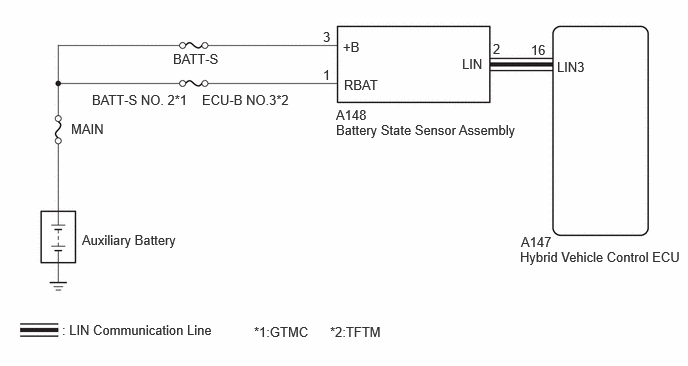
CAUTION / NOTICE / HINT
- NOTICE:
- ·
Inspect the fuses for circuits related to this system before performing the following procedure.
·When P162B87 (Lost Communication with Battery Monitor Module Missing Message) is output at the same time, perform troubleshooting for P162B87 (Lost Communication with Battery Monitor Module Missing Message) first.
PROCEDURE
Check installation condition of the battery state sensor assembly.
- Result:
Proceed to OK NG
OK
NG
Check that the battery state sensor assembly connector is securely connected.
- OK:
The connector is securely connected.
Disconnect the battery state sensor assembly connector.
Check the connector case and terminals for deformation or corrosion.
- OK:
No deformation or corrosion.
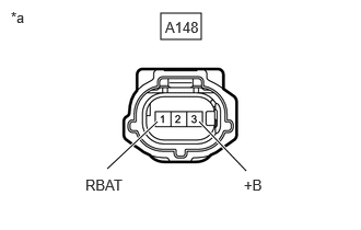
| *a | Front view of wire harness connector
(to Battery State Sensor Assembly) |
Measure the voltage according to the value(s) in the table below.
- Standard Voltage:
Tester Connection Condition Specified Condition A148-3 (+B) - Body ground Power switch off 11 to 14 V A148-1 (RBAT) - Body ground Power switch off 11 to 14 V
- Result:
Proceed to OK NG
OK
NG