HEATING / AIR CONDITIONING AIR CONDITIONING SYSTEM(for Automatic Air Conditioning System) TERMINALS OF ECU
AIR CONDITIONING AMPLIFIER ASSEMBLY
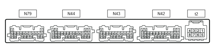
Disconnect the N42 and N44 air conditioning amplifier assembly connectors.
Measure the voltage and resistance according to the value(s) in the table below.
| Terminal No.
(Symbol) |
Wiring Color | Terminal Description | Condition | Specified Condition |
|---|---|---|---|---|
| N42-5 (B) - Body ground | P - Body ground | Power source (Back-up) | Always | 11 to 14 V |
| N42-6 (IG+) - Body ground | P - Body ground*2
V - Body ground*3 |
Power source (IG) | Ignition switch ON | 11 to 14 V |
| Ignition switch off | Below 1 V | |||
| N42-17 (GND) - Body ground | W-B - Body ground | Ground | Always | Below 1 Ω |
| N44-1 (+B2) - Body ground*1 | P - Body ground | Power source (Back-up) | Always | 11 to 14 V |
| N44-4 (GND2) - Body ground* | W-B - Body ground | Ground | Always | Below 1 Ω |
*1: w/ Integration Control Panel
*2: for Van
*3: for Wagon
Reconnect the N42 and N44 air conditioning amplifier assembly connectors.
Measure the voltage, resistance and pulse according to the value(s) in the table below.
| Terminal No.
(Symbol) |
Wiring Color | Terminal Description | Condition | Specified Condition |
|---|---|---|---|---|
| N79-8 (TR) - N79-14 (SG-6)*5, *6 | P - L | Rear room temperature sensor signal | ·
Ignition switch ON ·
AUTO switch: On ·
Cabin temperature: 25°C (77°F) |
1.05 to 1.45 V |
·
Ignition switch ON ·
AUTO switch: On ·
Cabin temperature: 40°C (104°F) |
0.64 to 0.87 V | |||
| N79-11 (TEC) - N79-15 (SG-8)*5, *6 | V - B | Rear evaporator temperature sensor signal | ·
Ignition switch ON ·
Evaporator temperature: 0°C (32°F) |
2.0 to 2.4 V |
·
Ignition switch ON ·
Evaporator temperature: 15°C (59°F) |
1.4 to 1.8 V | |||
| N79-14 (SG-6) - Body ground*5, *6 | L - Body ground | Ground for sensor | Always | Below 1 Ω |
| N79-15 (SG-8) - Body ground*5, *6 | B - Body ground | Ground for sensor | Always | Below 1 Ω |
| N79-16 (RNNO) - Body ground*4 | GR - Body ground | No. 2 ion generator sub-assembly operation signal | ·
Ignition switch ON ·
Blower switch: LO |
Below 1 V |
·
Ignition switch ON ·
Blower switch: Off |
11 to 14 V | |||
| N79-18 (RNIN) - Body ground*4 | W - Body ground | No. 2 ion generator sub-assembly condition signal | ·
Ignition switch ON ·
Blower switch: LO ·
"nanoe": On |
Below 1 V |
·
Ignition switch ON ·
Blower switch: Off ·
"nanoe": Off |
4.75 to 5.25 V | |||
| N44-2 (RBBU) - N44-3 (RBUG)*5 | R - GR | Power supply for BUS IC | Always | 11 to 14 V |
| N44-3 (RBUG) - Body ground*5 | GR - Body ground | Ground for BUS IC | Always | Below 1 Ω |
| N44-7 (RBUS) - N44-3 (RBUG)*5 | B - GR | BUS IC control signal | Ignition switch ON | Pulse generation
(See waveform 3) |
| N44-10 (BLWH) - Body ground*5, *6 | W - Body ground | Blower switch signal | ·
Ignition switch ON ·
Blower switch: LO |
Pulse generation
(See waveform 2) |
| N44-20 (RLIN) - Body ground*5, *6 | G - Body ground | LIN communication signal | Ignition switch ON | Pulse generation
(See waveform 1) |
| N43-3 (SG-1) - Body ground | LG - Body ground | Ground for sensor | Always | Below 1 Ω |
| N43-5 (TR) - Body ground | B - Body ground | Room temperature sensor signal | ·
Ignition switch ON ·
A/C switch: On ·
Cabin temperature: 25°C (77°F) |
1.05 to 1.45 V |
·
Ignition switch ON ·
A/C switch: On ·
Cabin temperature: 40°C (104°F) |
0.64 to 0.87 V | |||
| N43-6 (PRE) - N43-15 (SG-4) | B - GR | Air conditioner pressure sensor signal | ·
Engine running ·
Air conditioning system operating ·
Refrigerant pressure: Normal pressure (below 3025 kPa [30.8 kgf/cm2, 439 psi] and higher than 176 kPa [1.8 kgf/cm2, 26 psi]) |
0.74 to 4.61 V |
·
Engine running ·
Air conditioning system operating ·
Refrigerant pressure: Abnormal pressure (less than 176 kPa (1.8 kgf/cm2, 26 psi)) |
Below 0.74 V | |||
·
Engine running ·
Air conditioning system operating ·
Refrigerant pressure: Abnormal pressure (more than 3025 kPa (30.8 kgf/cm2, 439 psi)) |
4.61 V or higher | |||
| N43-11 (S5-3) - Body ground | L - Body ground | Power source of sensor | Ignition switch off → ON | Below 1 V → 4.75 to 5.25 V |
| N43-12 (LOCK) - Body ground | B - Body ground | Air conditioning lock sensor signal | ·
Engine running ·
Blower switch: LO ·
A/C switch: On |
Pulse generation
(See waveform 4) |
| N43-14 (SG-5) - Body ground | W - Body ground | Ground for sensor | Always | Below 1 Ω |
| N43-15 (SG-4) - Body ground | GR - Body ground | Ground for sensor | Always | Below 1 Ω |
| N43-16 (PTC2) - Body ground*1 | V - Body ground | Quick heater assembly operation signal | ·
Ignition switch ON ·
Temperature setting: MAX HOT ·
A/C switch: On ·
Ambient temperature: 0°C (32°F) or lower ·
Engine coolant temperature: 62.5°C (144.5°F) or lower ·
Blower switch: Off → LO (after 20 seconds) |
11 to 14 V → Below 1 V |
| N43-17 (PTC3) - Body ground*1 | L - Body ground | Quick heater assembly operation signal | ·
Ignition switch ON ·
Temperature setting: MAX HOT ·
A/C switch: On ·
Ambient temperature: 0°C (32°F) or lower ·
Engine coolant temperature: 62.5°C (144.5°F) or lower ·
Blower switch: Off → LO (after 30 seconds) |
11 to 14 V → Below 1 V |
| N43-19 (MGC) - Body ground | G - Body ground | Magnetic clutch operation signal | ·
Engine running ·
Blower switch: LO ·
A/C switch: Off or on (magnet clutch off) |
11 to 14 V |
·
Engine running ·
Blower switch: LO ·
A/C switch: On (magnet clutch on) |
Below 1 V | |||
| N43-21 (MGCA) - Body ground*2 | P - Body ground | Viscous heater with magnetic clutch assembly operation signal | ·
Engine running ·
Blower switch: LO ·
A/C switch: On ·
Heater switch assembly: Off or on (magnet clutch off) |
11 to 14 V |
·
Engine running ·
Blower switch: LO ·
A/C switch: On ·
Heater switch assembly: On (magnet clutch on) |
Below 1 V | |||
| N41-18 (CFN+) - Body ground*7 | L - Body ground | CDS FAN relay drive output signal | ·
Engine running ·
Ambient temperature: 28°C (82°F) or lower ·
Air conditioning system operating ·
Condenser fan system operating |
Below 1 V |
| N42-1 (CANL) | - | CAN communication line | - | - |
| N42-2 (CANH) | - | CAN communication line | - | - |
| N42-4 (NAIN) - Body ground*4 | GR - Body ground | No. 1 ion generator sub-assembly condition signal | ·
Ignition switch ON ·
Blower switch: LO |
Below 1 V |
·
Ignition switch ON ·
Blower switch: Off |
4.75 to 5.25 V | |||
| N42-7 (LIN1) - Body ground | V - Body ground | LIN communication signal | Ignition switch ON | Pulse generation
(See waveform 1) |
| N42-12 (SWVC) - Body ground*2, *3 | R - Body ground*2
L - Body ground*3 |
Heater switch assembly operation signal*2
Idle up switch operation signal*3 |
·
Engine running ·
Blower switch: LO ·
A/C switch: On ·
Heater switch assembly: Off → on*2 ·
Idle up switch: Off → on*3 |
11 to 14 V → Below 1 V |
| N42-21 (BLW) - Body ground | Y - Body ground | Blower motor speed control signal | ·
Ignition switch ON ·
Blower switch: LO |
Pulse generation
(See waveform 2) |
| N42-22 (RMGV) - Body ground*5, *6 | L - Body ground | Rear magnet valve signal | ·
Engine running ·
A/C switch: On ·
A/C switch (for Rear Automatic Air Conditioning): On ·
Blower switch: LO ·
Rear expansion value: Off → on |
11 to 14 V → Below 1 V |
| N42-23 (PTC1) - Body ground*1 | W - Body ground | Quick heater assembly operation signal | ·
Ignition switch ON ·
Temperature setting: MAX HOT ·
A/C switch: On ·
Ambient temperature: 0°C (32°F) or lower ·
Engine coolant temperature: 62.5°C (144.5°F) or lower ·
Blower switch: Off → LO (after 10 seconds) |
11 to 14 V → Below 1 V |
| N42-24 (NANO) - Body ground*4 | G - Body ground | No. 1 ion generator sub-assembly operation signal | ·
Ignition switch ON ·
Blower switch: LO |
Below 1 V |
·
Ignition switch ON ·
Blower switch: Off |
11 to 14 V | |||
| t2-2 (BUSG) - Body ground | - | Ground for BUS IC | Always | Below 1 Ω |
| t2-3 (BUS) - t2-2 (BUSG) | - | BUS IC control signal | Ignition switch ON | Pulse generation
(See waveform 3) |
| t2-4 (BUSB) - t2-2 (BUSG) | - | Power supply for BUS IC | Always | 11 to 14 V |
| t2-5 (SG-3) - Body ground | - | Ground for sensor | Always | Below 1 Ω |
| t2-6 (TE) - t2-5 (SG-3) | - | No. 1 cooler thermistor signal | ·
Ignition switch ON ·
A/C switch: On ·
Evaporator temperature: 0°C (32°F) |
1.7 to 2.1 V |
·
Ignition switch ON ·
A/C switch: On ·
Evaporator temperature: 15°C (59°F) |
0.9 to 1.3 V |
*1: w/ PTC Heater
*2: w/ Viscous Heater
*3: w/ Idle Up Switch
*4: w/ Ion Generator
*5: w/ Integration Control Panel (for Rear Automatic Air Conditioning)
*6: w/ Integration Control Panel (for Rear Automatic Cooler)
*7: w/ Condenser Blower Motor
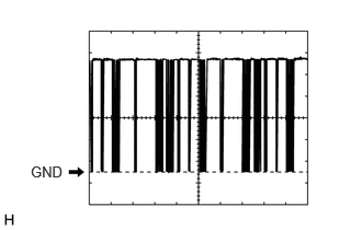
Waveform 1:
| Item | Content |
|---|---|
| Terminal No. | N42-7 (LIN1) - Body ground
N79-18 (RNIN) - Body ground* |
| Tool Setting | 2 V/DIV., 20 μs./DIV. |
| Vehicle Condition | Ignition switch ON |
*: w/ Integration Control Panel
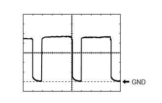
Waveform 2:
| Item | Content |
|---|---|
| Terminal No. | N42-21 (BLW) - Body ground
N44-10 (BLWH) - Body ground* |
| Tool Setting | 1 V/DIV., 500 μs./DIV. |
| Vehicle Condition | ·
Ignition switch ON ·
Blower switch: LO |
*: w/ Integration Control Panel
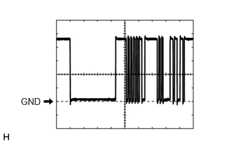
Waveform 3:
| Item | Content |
|---|---|
| Terminal No. | t2-3 (BUS) - t2-2 (BUSG)
N44-7 (RBUS) - N44-3 (RBUG)* |
| Tool Setting | 2 V/DIV., 20 μs./DIV. |
| Vehicle Condition | Ignition switch ON |
*: w/ Integration Control Panel (for Rear Automatic Air Conditioning)
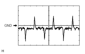
Waveform 4:
| Item | Content |
|---|---|
| Terminal No. | N43-12 (LOCK) - Body ground |
| Tool Setting | 200 mV/DIV., 10 ms./DIV. |
| Condition | ·
Engine running ·
Blower switch: LO ·
A/C switch: On |
AIR CONDITIONING CONTROL ASSEMBLY

Disconnect the N55 air conditioning control assembly connector.
Measure the voltage and resistance according to the value(s) in the table below.
| Terminal No.
(Symbol) |
Wiring Color | Terminal Description | Condition | Specified Condition |
|---|---|---|---|---|
| N55-13 (GND) - Body ground | W-B - Body ground | Ground | Always | Below 1 Ω |
| N55-9 (IG+) - Body ground | GR - Body ground | Power source (IG) | Ignition switch off | Below 1 V |
| Ignition switch ON | 11 to 14 V |
Reconnect the N55 air conditioning control assembly connector.
Check for waveform according to the value(s) in the table below.
| Terminal No.
(Symbol) |
Wiring Color | Terminal Description | Condition | Specified Condition |
|---|---|---|---|---|
| N55-7 (LIN1) - Body ground | V - Body ground | LIN communication | Ignition switch ON | Pulse generation
(See waveform 1) |
Waveform 1:
| Item | Content |
|---|---|
| Terminal No. | N55-7 (LIN1) - Body ground |
| Tool Setting | 2 V/DIV., 20 μs./DIV. |
| Vehicle Condition | Ignition switch ON |
INTEGRATION CONTROL AND PANEL ASSEMBLY (w/ Integration Control Panel)
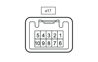
Disconnect the a17 integration control and panel assembly connector.
Measure the voltage and resistance according to the value(s) in the table below.
| Terminal No.
(Symbol) |
Wiring Color | Terminal Description | Condition | Specified Condition |
|---|---|---|---|---|
| a17-6 (E) - Body ground | LA - Body ground | Ground | Always | Below 1 Ω |
| a17-5 (IG) - Body ground | LA-GR - Body ground | Power source (IG) | Ignition switch off | Below 1 V |
| Ignition switch ON | 11 to 14 V |
Reconnect the a17 air conditioning control assembly connector.
Check for waveform according to the value(s) in the table below.
| Terminal No.
(Symbol) |
Wiring Color | Terminal Description | Condition | Specified Condition |
|---|---|---|---|---|
| a17-7 (RLIN) - Body ground | Y - Body ground | LIN communication | Ignition switch ON | Pulse generation
(See waveform 1) |
| a17-8 (CXPI) - Body ground | GR - Body ground | CXPI communication | Ignition switch ON | Pulse generation
(See waveform 2) |
Waveform 1:
| Item | Content |
|---|---|
| Terminal No. | a17-7 (RLIN) - Body ground |
| Tool Setting | 2 V/DIV., 20 μs./DIV. |
| Vehicle Condition | Ignition switch ON |
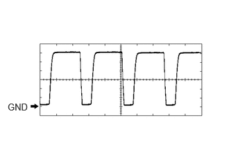
Waveform 2:
| Item | Content |
|---|---|
| Terminal No. | a17-8 (CXPI) - Body ground |
| Tool Setting | 2 V/DIV., 20 μs./DIV. |
| Vehicle Condition | Ignition switch ON |
ECM
for 1GD-FTV (w/ Urea SCR System):
for 1GD-FTV (w/ Exhaust Gas Temperature Sensor for EGR):Engine / Hybrid System>1GD-FTV (ENGINE CONTROL)>ECD SYSTEM (w/ Exhaust Gas Temperature Sensor for EGR)>TERMINALS OF ECM202208,999999,_51,_078856,_0395991,RM100000002570O,
for 1GD-FTV (for w/ Urea SCR System):Engine / Hybrid System>1GD-FTV (ENGINE CONTROL)>ECD SYSTEM (w/ Urea SCR System)>TERMINALS OF ECM202208,999999,_51,_078856,_0382589,RM100000002569O,
MAIN BODY ECU (MULTIPLEX NETWORK BODY ECU)
COMBINATION METER ASSEMBLY