RM35X0E _59 Vehicle Exterior _079320 WIPER / WASHER _0385301 WIPER AND WASHER SYSTEM J

WIPER / WASHER  WIPER AND WASHER SYSTEM  Rear Wiper Motor Circuit  


DESCRIPTION

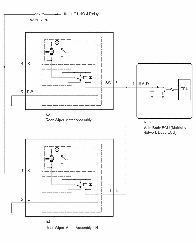
This circuit is the power source circuit for the rear wiper motor assembly.

WIRING DIAGRAM

except Double Swing Out Type:
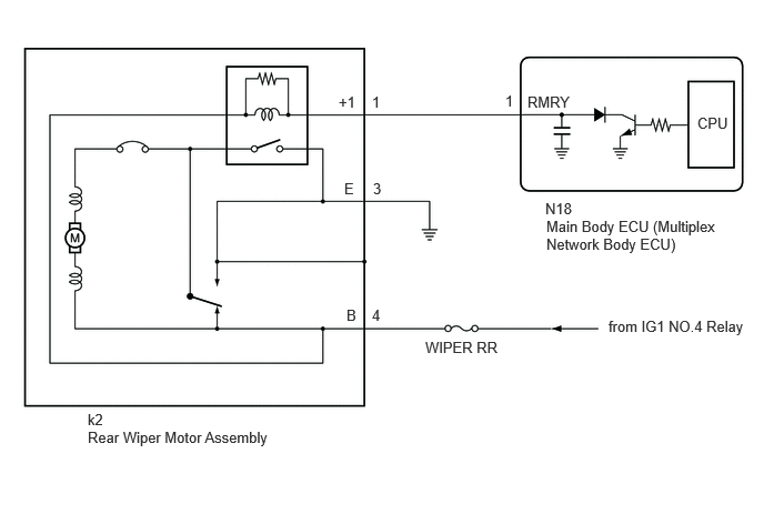

E415848E01
0.823,3.854 1.135,4.052 0.313,0.198 10 false k2 0.823,4.021 2.615,4.25 1.792,0.229 10 false Rear Wiper Motor Assembly 3.177,0.875 3.49,1.073 0.313,0.198 10 false +1 3.49,0.875 3.646,1.073 0.156,0.198 10 false 1 4.74,0.865 4.896,1.063 0.156,0.198 10 false 1 4.948,0.875 5.563,1.073 0.615,0.198 10 false RMRY 5.115,1.875 5.573,2.073 0.458,0.198 10 false N18 5.125,2.042 6.771,2.417 1.646,0.375 10 false Main Body ECU (Multiplex Network Body ECU) 6.542,1.073 6.938,1.302 0.396,0.229 10 false CPU 3.25,2.875 3.563,3.073 0.313,0.198 10 false B 3.49,2.875 3.646,3.073 0.156,0.198 10 false 4 3.99,3.177 4.76,3.375 0.771,0.198 10 false WIPER RR 5.708,2.979 7.063,3.208 1.354,0.229 10 false from IG1 NO.4 Relay 3.229,1.688 3.385,1.885 0.156,0.198 10 false E 3.5,1.688 3.656,1.885 0.156,0.198 10 false 3


for Double Swing Out Type:


E496561E01
1.104,0.646 1.885,0.823 0.781,0.177 10 false WIPER RR 2.344,0.417 3.688,0.635 1.344,0.219 10 false from IG1 NO.4 Relay 6.604,3.156 6.969,3.365 0.365,0.208 10 false CPU 5.073,2.969 5.688,3.167 0.615,0.198 10 false RMRY 5.24,4.583 6.865,5.063 1.625,0.479 10 false Main Body ECU (Multiplex Network Body ECU) 5.26,4.375 5.719,4.573 0.458,0.198 10 false N18 4.844,2.958 5,3.156 0.156,0.198 10 false 1 1.667,4.292 3.688,4.5 2.021,0.208 10 false Rear Wiper Motor Assembly LH 1.677,4.083 1.99,4.281 0.313,0.198 10 false k5 1.667,8.229 3.688,8.438 2.021,0.208 10 false Rear Wiper Motor Assembly RH 1.677,8 1.99,8.198 0.313,0.198 10 false h2 0.76,3.271 0.917,3.469 0.156,0.198 10 false 5 0.99,3.271 1.302,3.469 0.313,0.198 10 false EW 0.76,7.188 0.917,7.385 0.156,0.198 10 false 5 1,7.188 1.156,7.385 0.156,0.198 10 false E 3.781,2.938 4.24,3.135 0.458,0.198 10 false LSW 4.219,2.938 4.375,3.135 0.156,0.198 10 false 3 4.229,6.875 4.385,7.073 0.156,0.198 10 false 3 3.906,6.875 4.219,7.073 0.313,0.198 10 false +1 0.771,2.229 0.927,2.427 0.156,0.198 10 false 4 1.01,2.24 1.167,2.438 0.156,0.198 10 false S 0.771,6.146 0.927,6.344 0.156,0.198 10 false 4 1,6.146 1.156,6.344 0.156,0.198 10 false B


CAUTION / NOTICE / HINT

NOTICE:
·

Inspect the fuse of circuits related to this system before performing the following procedure.

·

If the main body ECU (multiplex network body ECU) is replaced, refer to the Service Bulletin.


PROCEDURE

1.PERFORM ACTIVE TEST USING GTS (REAR WIPER OPERATION)
a.

Connect the GTS to the DLC3.


b.

Turn the ignition switch to ON.


c.

Turn the GTS on.


d.

Enter following menus: Body Electrical / Main Body / Active Test.


e.

Perform the Active Test according to the display on the GTS.

Body Electrical > Main Body > Active Test
Tester Display Measurement Item Control Range Diagnostic Note
Rear Wiper Operation
·

Function to operate the rear wiper motor assembly (except Double Swing Out Type)

·

Function to operate the rear wiper motor assembly LH and RH (for Double Swing Out Type)


OFF or ON -
Body Electrical > Main Body > Active Test
Tester Display
Rear Wiper Operation
50004 123 90
OK:

Rear wiper motor assembly operates normally.


Result:
Proceed to
OK
NG


OK

NG

2.CHECK VEHICLE TYPE
a.

Check the vehicle type.


Result:
Result Proceed to
except Double Swing Out Type A
for Double Swing Out Type B


A

3.INSPECT REAR WIPER MOTOR ASSEMBLY

B

6.CHECK VEHICLE CONDITION
3.INSPECT REAR WIPER MOTOR ASSEMBLY

OK

4.CHECK HARNESS AND CONNECTOR (REAR WIPER MOTOR ASSEMBLY - BATTERY AND BODY GROUND)

NG

4.CHECK HARNESS AND CONNECTOR (REAR WIPER MOTOR ASSEMBLY - BATTERY AND BODY GROUND)
a.
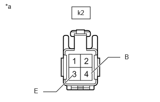
E415569C01
1.542,0.146 1.938,0.406 0.396,0.26 1.958,1.573 2.323,1.229 2.323,1.229 2.583,1.229 true 1.573,1.604 1.208,1.969 1.208,1.969 0.927,1.969 true 1.667,0.188 1.979,0.385 0.313,0.198 10 false k2 2.677,1.135 2.99,1.333 0.313,0.198 10 false B 0.729,1.865 0.885,2.063 0.156,0.198 10 false E 0.115,0.052 0.427,0.25 0.313,0.198 10 false *a
*a Front view of wire harness connector
(to Rear Wiper Motor Assembly)


Disconnect the rear wiper motor assembly connector.


b.

Measure the resistance according to the value(s) in the table below.

Standard Resistance:
Tester Connection Condition Specified Condition
k2-3 (E) - Body Ground Always Below 1 Ω


c.

Measure the voltage according to the value(s) in the table below.

Standard Voltage:
Tester Connection Swicth Condition Specified Condition
k2-4 (B) - Body ground Ignition switch ON 11 to 14 V


Result:
Proceed to
OK
NG


OK

5.CHECK HARNESS AND CONNECTOR (REAR WIPER MOTOR ASSEMBLY - MAIN BODY ECU [MULTIPLEX NETWORK BODY ECU])

NG

REPAIR OR REPLACE HARNESS OR CONNECTOR

5.CHECK HARNESS AND CONNECTOR (REAR WIPER MOTOR ASSEMBLY - MAIN BODY ECU [MULTIPLEX NETWORK BODY ECU])
a.

Disconnect the k2 rear wiper motor assembly connector.


b.

Disconnect the N18 main body ECU (multiplex network body ECU) connector.


c.

Measure the resistance according to the value(s) in the table below.

Standard Resistance:
Tester Connection Condition Specified Condition
k2-1 (+1) - N18-1 (RMRY) Always Below 1 Ω
k2-1 (+1) or N18-1 (RMRY) - Body ground Always 10 kΩ or higher


Result:
Proceed to
OK
NG


OK

NG

REPAIR OR REPLACE HARNESS OR CONNECTOR

6.CHECK VEHICLE CONDITION
a.

Check the vehicle condition.


Result:
Result Proceed to
Rear wiper motor assembly LH does not operates. A
Rear wiper motor assembly RH does not operates. B
Both rear wiper motor assembly LH and RH do not operates. C


A

7.INSPECT REAR WIPER MOTOR ASSEMBLY LH

B

9.INSPECT REAR WIPER MOTOR ASSEMBLY RH

C

11.CHECK HARNESS AND CONNECTOR (REAR WIPER MOTOR ASSEMBLY LH - BATTERY AND BODY GROUND)
7.INSPECT REAR WIPER MOTOR ASSEMBLY LH

OK

8.CHECK HARNESS AND CONNECTOR (REAR WIPER MOTOR ASSEMBLY LH - BATTERY AND BODY GROUND)

NG

8.CHECK HARNESS AND CONNECTOR (REAR WIPER MOTOR ASSEMBLY LH - BATTERY AND BODY GROUND)
a.
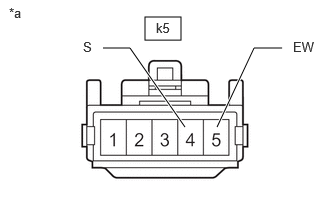
E496562C01
1.51,0.177 1.885,0.417 0.375,0.24 1.073,0.5 1.354,0.5 1.354,0.5 1.927,1.323 true 2.938,0.5 2.646,0.5 2.646,0.5 2.26,1.323 true 0.094,0.052 0.396,0.24 0.302,0.188 10 false *a 1.625,0.208 1.938,0.406 0.313,0.198 10 false k5 0.865,0.406 1.021,0.604 0.156,0.198 10 false S 3.052,0.406 3.354,0.625 0.302,0.219 10 false EW
*a Front view of wire harness connector
(to Rear Wiper Motor Assembly LH)


Disconnect the rear wiper motor assembly LH connector.


b.

Measure the resistance according to the value(s) in the table below.

Standard Resistance:
Tester Connection Condition Specified Condition
k5-5 (EW) - Body Ground Always Below 1 Ω


c.

Measure the voltage according to the value(s) in the table below.

Standard Voltage:
Tester Connection Switch Condition Specified Condition
k5-4 (S) - Body ground Ignition switch ON 11 to 14 V


Result:
Proceed to
OK
NG


OK

REPAIR OR REPLACE HARNESS OR CONNECTOR (REAR WIPER MOTOR ASSEMBLY LH - MAIN BODY ECU [MULTIPLEX NETWORK BODY ECU])

NG

REPAIR OR REPLACE HARNESS OR CONNECTOR

9.INSPECT REAR WIPER MOTOR ASSEMBLY RH

OK

10.CHECK HARNESS AND CONNECTOR (REAR WIPER MOTOR ASSEMBLY RH - BATTERY AND BODY GROUND)

NG

10.CHECK HARNESS AND CONNECTOR (REAR WIPER MOTOR ASSEMBLY RH - BATTERY AND BODY GROUND)
a.
E496562C02
1.51,0.177 1.885,0.417 0.375,0.24 1.073,0.5 1.354,0.5 1.354,0.5 1.927,1.323 true 2.938,0.5 2.646,0.5 2.646,0.5 2.26,1.323 true 0.094,0.052 0.396,0.24 0.302,0.188 10 false *a 1.625,0.208 1.938,0.406 0.313,0.198 10 false h2 0.865,0.406 1.021,0.604 0.156,0.198 10 false B 3.042,0.396 3.344,0.615 0.302,0.219 10 false E
*a Front view of wire harness connector
(to Rear Wiper Motor Assembly RH)


Disconnect the rear wiper motor assembly RH connector.


b.

Measure the resistance according to the value(s) in the table below.

Standard Resistance:
Tester Connection Condition Specified Condition
h2-5 (E) - Body Ground Always Below 1 Ω


c.

Measure the voltage according to the value(s) in the table below.

Standard Voltage:
Tester Connection Switch Condition Specified Condition
h2-4 (B) - Body ground Ignition switch ON 11 to 14 V


Result:
Proceed to
OK
NG


OK

REPAIR OR REPLACE HARNESS OR CONNECTOR (REAR WIPER MOTOR ASSEMBLY RH - MAIN BODY ECU [MULTIPLEX NETWORK BODY ECU])

NG

REPAIR OR REPLACE HARNESS OR CONNECTOR

11.CHECK HARNESS AND CONNECTOR (REAR WIPER MOTOR ASSEMBLY LH - BATTERY AND BODY GROUND)
a.
E496562C01
1.51,0.177 1.885,0.417 0.375,0.24 1.073,0.5 1.354,0.5 1.354,0.5 1.927,1.323 true 2.938,0.5 2.646,0.5 2.646,0.5 2.26,1.323 true 0.094,0.052 0.396,0.24 0.302,0.188 10 false *a 1.625,0.208 1.938,0.406 0.313,0.198 10 false k5 0.865,0.406 1.021,0.604 0.156,0.198 10 false S 3.052,0.406 3.354,0.625 0.302,0.219 10 false EW
*a Front view of wire harness connector
(to Rear Wiper Motor Assembly LH)


Disconnect the rear wiper motor assembly LH connector.


b.

Measure the resistance according to the value(s) in the table below.

Standard Resistance:
Tester Connection Condition Specified Condition
k5-5 (EW) - Body Ground Always Below 1 Ω


c.

Measure the voltage according to the value(s) in the table below.

Standard Voltage:
Tester Connection Switch Condition Specified Condition
k5-4 (S) - Body ground Ignition switch ON 11 to 14 V


Result:
Proceed to
OK
NG


OK

12.CHECK HARNESS AND CONNECTOR (REAR WIPER MOTOR ASSEMBLY LH - MAIN BODY ECU [MULTIPLEX NETWORK BODY ECU])

NG

REPAIR OR REPLACE HARNESS OR CONNECTOR

12.CHECK HARNESS AND CONNECTOR (REAR WIPER MOTOR ASSEMBLY LH - MAIN BODY ECU [MULTIPLEX NETWORK BODY ECU])
a.

Disconnect the k5 rear wiper motor assembly LH connector.


b.

Disconnect the N18 main body ECU (multiplex network body ECU) connector.


c.

Measure the resistance according to the value(s) in the table below.

Standard Resistance:
Tester Connection Condition Specified Condition
k5-3 (LSW) - N18-1 (RMRY) Always Below 1 Ω
k5-3 (LSW) or N18-1 (RMRY) - Body ground Always 10 kΩ or higher


Result:
Proceed to
OK
NG


OK

NG

REPAIR OR REPLACE HARNESS OR CONNECTOR