PARK ASSIST / MONITORING BLIND SPOT MONITOR SENSOR ADJUSTMENT
PROCEDURE

 1.PERFORM BLIND SPOT MONITOR BEAM AXIS CONFIRMATION
- HINT:
-
The blind spot monitor beam axis confirmation is performed to confirm whether the sensor's beam axis is correct, and perform adjustment of the beam axis by using a reflector.
When performing the blind spot monitor beam axis confirmation, move the vehicle to a place where the space shown in the illustration can be secured.
- NOTICE:
- ·
Perform this inspection on level ground.
·Make sure that there are no metal objects around the vehicle or on the ground.
·Unload the vehicle before beginning the inspection.
·Confirm that the tire pressure is correct before beginning the inspection.
·Do not place any objects other than the reflector (such as a large metallic object) in or allow people to enter the inspection area (W 6 m [19.68 ft.] x L 6 m [19.68 ft.] x H 3 m [9.84 ft.] ) shown in the illustration.
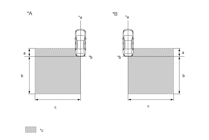
| *A | Left Side Of Vehicle | *B | Right Side Of Vehicle |
| *a | Vehicle Center Line | *b | Edge of Rear Bumper |
| *c | Inspection Area | - | - |
- Standard:
Location Measurement a 1 m (3.28 ft.) b 5 m (16.40 ft.) c 6 m (19.68 ft.)
Place the reflector.
except Double Swing Out Type:
Hang a weight with a pointed tip from the center of the symbol emblem, and mark the rear center point of the vehicle (point A) on the ground.
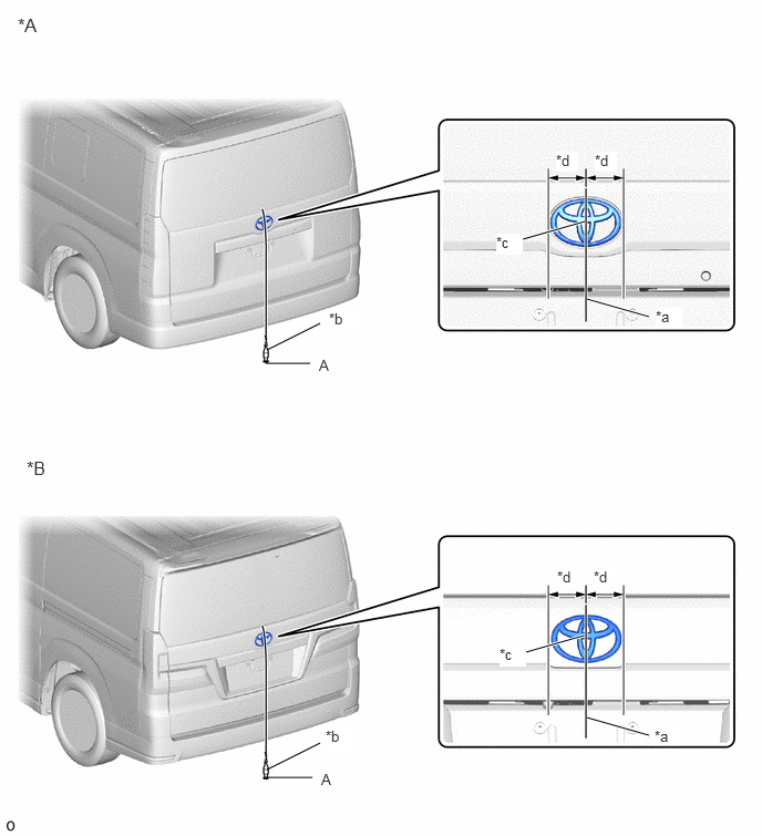
| *A | except Wagon | *B | for Wagon |
| *a | String | *b | Weight |
| *c | Center Point | *d | Bilateral Symmetry |
- HINT:
-
Lightly flick the string with your fingers several times to confirm that the string is aligned with mark A.
for Double Swing Out Type:
Hang a weight with a pointed tip from the center of the back door panel end face, and mark the rear center point of the vehicle (point A) on the ground.
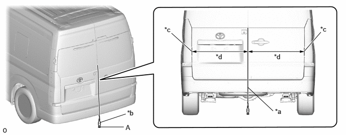
| *a | String | *b | Weight |
| *c | Back Door Panel End Face | *d | Bilateral Symmetry |
- HINT:
-
Lightly flick the string with your fingers several times to confirm that the string is aligned with mark A.
Hang a weight with a pointed tip from the center of the radiator grille (or front panel) emblem, and mark the front center point of the vehicle (point B) on the ground.
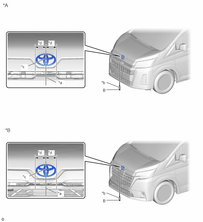
| *A | except Wagon | *B | for Wagon |
| *a | String | *b | Weight |
| *c | Center Point | *d | Bilateral Symmetry |
- HINT:
-
Lightly flick the string with your fingers several times to confirm that the string is aligned with mark B.
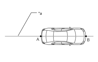
| *a | Vehicle Center Line |
Draw a vehicle center line so that it passes through mark A and B (front and rear center points).
except Wagon:
Enlarge and print out the poster shown in the illustration.
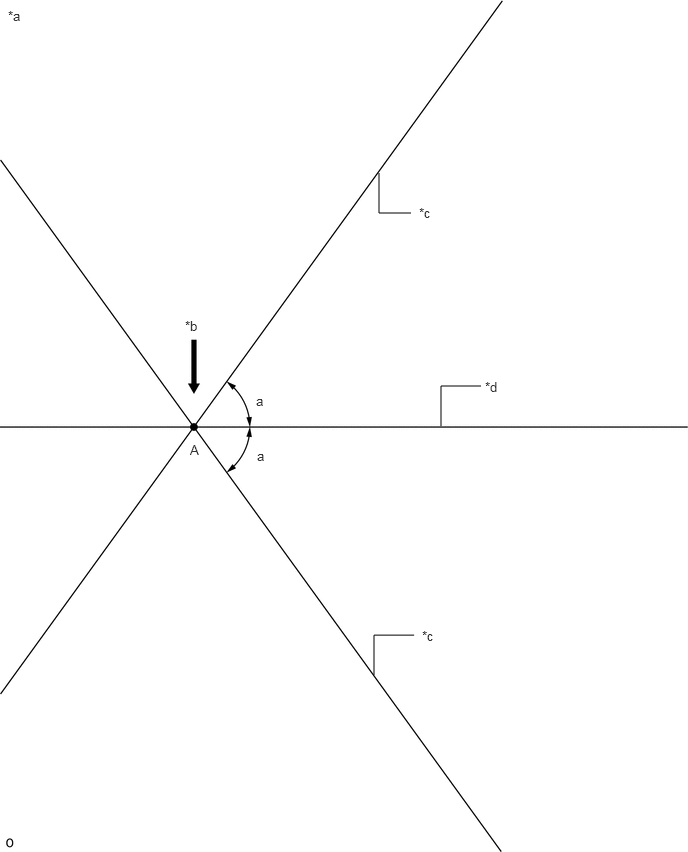
| *a | Poster | *b | Edge of Rear Bumper |
| *c | Line C | *d | Vehicle Center Line |
- Standard:
Part Angle a 54.1°
for Wagon:
Enlarge and print out the poster shown in the illustration.
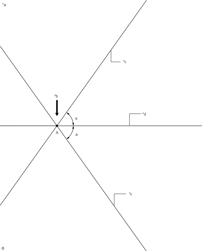
| *a | Poster | *b | Edge of Rear Bumper |
| *c | Line C | *d | Vehicle Center Line |
- Standard:
Part Angle a 54.4°
for Double Swing Out Type:
Enlarge and print out the poster shown in the illustration.
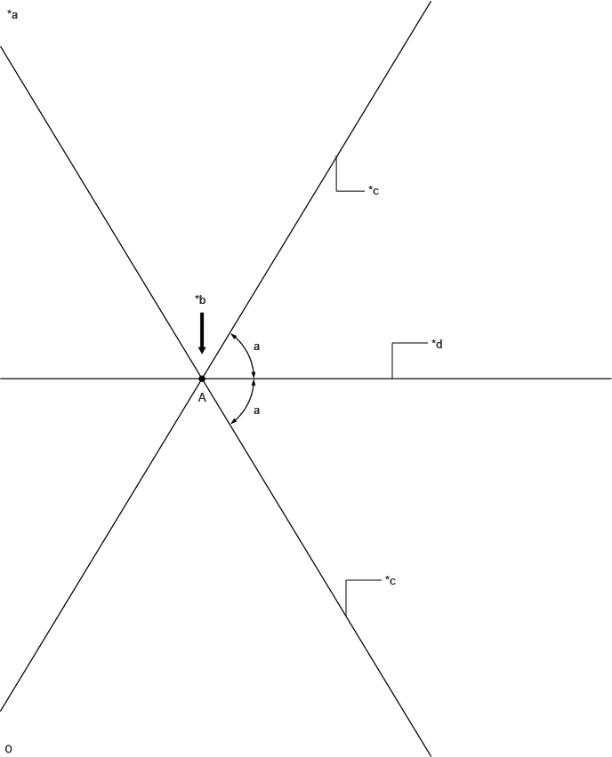
| *a | Poster | *b | Edge of Rear Bumper |
| *c | Line C | *d | Vehicle Center Line |
- Standard:
Part Angle a 58.8°
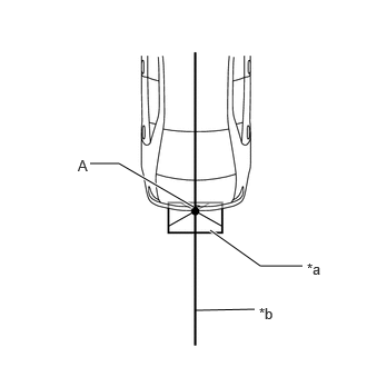
| *a | Poster |
| *b | Vehicle Center Line |
Attach the printed poster to the floor with the vehicle center line aligned with point A as shown in the illustration.
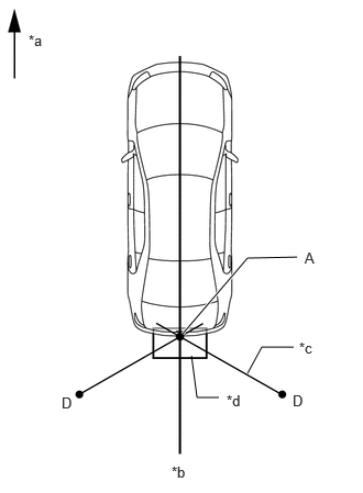
| *a | Vehicle Front |
| *b | Vehicle Center Line |
| *c | String |
| *d | Poster |
except Wagon:
Align a piece of string with line C and mark point D at a distance of 3074 mm (10.08 ft.) from point A.
| *a | Vehicle Front |
| *b | Vehicle Center Line |
| *c | String |
| *d | Poster |
for Wagon:
Align a piece of string with line C and mark point D at a distance of 3065 mm (10.05 ft.) from point A.
| *a | Vehicle Front |
| *b | Vehicle Center Line |
| *c | String |
| *d | Poster |
for Double Swing Out Type:
Align a piece of string with line C and mark point D at a distance of 3074 mm (10.08 ft.) from point A.
Set the reflector at the point D shown in the illustration below.
- SST
- 09870-60000 (09870-60010)
09870-60040
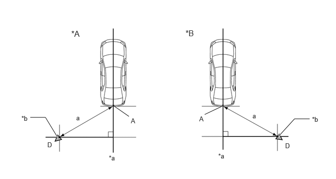
| *A | Left Side of Vehicle | *B | Right Side of Vehicle |
| *a | Vehicle Center Line | *b | Reflector |
- except Wagon:
- Standard:
Part Length a 3074 mm (10.08 ft.)
- for Wagon:
- Standard:
Part Length a 3065 mm (10.05 ft.)
- for Double Swing Out Type:
- Standard:
Part Length a 3074 mm (10.08 ft.)
- NOTICE:
- ·
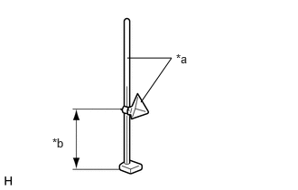 1.469,0.667 1.979,0.667 1.979,0.667 1.625,1.177 false 2.031,0.594 2.344,0.792 0.313,0.198 10 false *a 0.604,1.563 0.917,1.76 0.313,0.198 10 false *b
*a SST (reflector) *b 717.2 mm (2.35 ft.)
Set the reflector so that its center is 717.2 mm (2.35 ft.) above the ground.
·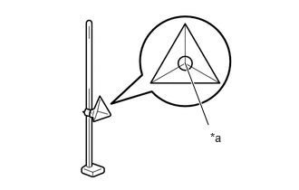 2.125,0.719 2.396,1.438 true 2.417,1.5 2.74,1.729 0.323,0.229 10 false *a
*a Center Of Triangular Pyramid
The center of the triangular pyramid is the reference point for the setting position and angle.
Perform the blind spot monitor beam axis display.
Turn the ignition switch off.
Connect the GTS to the DLC3.
Turn the ignition switch to ON.
Turn the blind spot monitor system on.
Turn the GTS on.
Enter the following menus: Body Electrical / Blind Spot Monitor Master or Blind Spot Monitor Slave / Utility / BSM Master Beam Axis Display or BSM Slave Beam Axis Display.
- HINT:
-
The slave beam is on the RH side and the master beam is on the LH side.
Part Name Tester Item Expression in Others Blind spot monitor sensor LH Blind Spot Monitor Master Blind spot monitor sensor LH (B) Blind spot monitor sensor RH Blind Spot Monitor Slave Blind spot monitor sensor RH (A)
- Body Electrical > Blind Spot Monitor Master > Utility
-
Tester Display BSM Master Beam Axis Display - 50005 313 4238
- Body Electrical > Blind Spot Monitor Slave > Utility
-
Tester Display BSM Slave Beam Axis Display - 50005 314 4239
Check the results displayed for the BSM beam axis display.
- Allowable Range:
Item Blind Spot Monitor Sensor RH (Slave) Blind Spot Monitor Sensor LH (Master) Angle -3.6 to +3.6° -3.6 to + 3.6°
- HINT:
-
If the displayed results are outside the permissible range, the following are possible causes. Therefore, implement countermeasures, check the blind spot monitor beam axis and perform the procedure again.
Possible Causes Countermeasure Incorrect SST (reflector) position Check the position of SST (reflector) and checking space and perform the procedure again A metallic object is located in the vicinity of the checking space Check the position of SST (reflector) and checking space and perform the procedure again The blind spot monitor sensor installation is abnormal Check the installation condition of the blind spot monitor sensor
Perform the blind spot monitor beam axis adjustment.
Enter the following menus: Body Electrical / Blind Spot Monitor Master or Blind Spot Monitor Slave / Utility / BSM Master Beam Axis Adjustment or BSM Slave Beam Axis Adjustment.
- Body Electrical > Blind Spot Monitor Master > Utility
-
Tester Display BSM Master Beam Axis Adjustment - 50005 313 4231
- Body Electrical > Blind Spot Monitor Slave > Utility
-
Tester Display BSM Slave Beam Axis Adjustment - 50005 314 4232
- HINT:
-
When values on the axis display are in the allowable range, performing this adjustment compensates for any deviation from the normal value.
2.PERFORM BLIND SPOT MONITOR SENSOR INSTALLATION CONDITION INSPECTION
- NOTICE:
- ·
Perform this inspection on level ground.
·Unload the vehicle before beginning the inspection.
·Confirm that the tire pressure is correct before beginning the inspection.
- HINT:
-
The blind spot monitor sensor installation condition inspection is performed to confirm whether the sensor is perpendicular to the floor surface (+/-2.2°) by using a digital angle gauge, and that the sensor is 46 to 54° from the line parallel to the vehicle center line.
Remove the rear bumper assembly.
Place the digital angle gauge on a level (gradient within 1%) and perform zero-point adjustment as shown in the illustration.
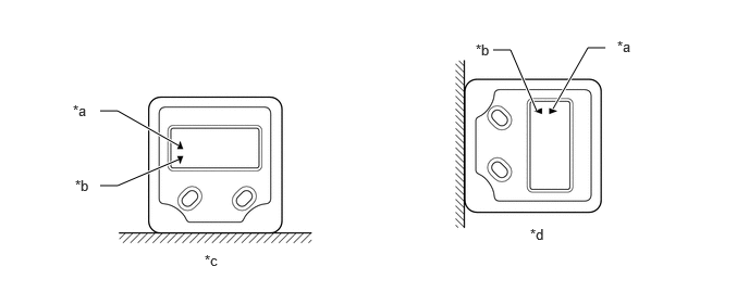
| *a | (+) | *b | (-) |
| *c | When Storing Zero Point | *d | After Storing Zero Point, Indicates 90° When Fully Horizontal |
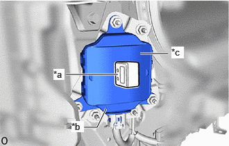
| *a | Digital Angle Gauge |
| *b | Blind Spot Monitor Sensor |
| *c | Outward Facing Surface |
Set the digital angle gauge to the outward facing surface of the blind spot monitor sensor as shown in the illustration, and check that the perpendicular angle of the blind spot monitor sensor is within the permissible range.
- HINT:
-
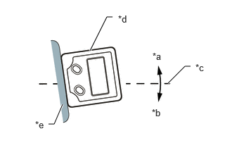 2.49,1.229 2.74,0.979 2.74,0.979 2.823,0.979 true 1.333,0.75 1.583,0.25 1.583,0.25 1.667,0.25 true 0.719,1.833 0.802,1.833 0.802,1.833 0.927,1.542 true 2.26,0.75 2.646,0.948 0.385,0.198 10 false *a 2.25,1.583 2.635,1.781 0.385,0.198 10 false *b 2.896,0.917 3.281,1.115 0.385,0.198 10 false *c 1.75,0.198 2.833,0.396 1.083,0.198 10 false *d 0.521,1.76 1.188,2.01 0.667,0.25 10 false *e
*a (+) *b (-) *c Horizontal Line *d Digital Angle Gauge *e Outward Facing Surface
-
The outward facing surface (installation angle) is positive (+) when it faces higher than horizontal.
- Standard:
Item Allowable Range Blind Spot Monitor Sensor RH (Slave) +87.8 to +92.2° Blind Spot Monitor Sensor LH (Master) +87.8 to +92.2°
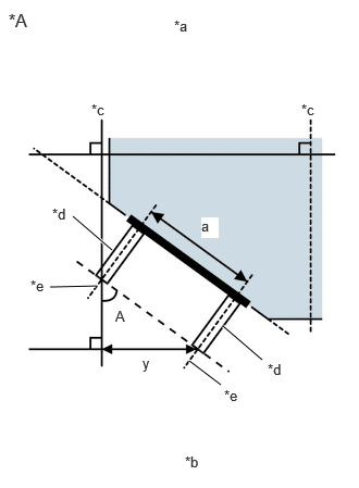
| *A | Vehicle Rear (LH) |
| *a | Vehicle Front |
| *b | Vehicle Rear |
| *c | Line Parallel to The Vehicle Center Line |
| *d | Stud Bolt |
| *e | Stud Bolt Center Line |
Using the sensor installation stud bolt center lines as a reference, check that the stud bolts are as shown in the illustration.
- Standard:
Dimension Specified Value a 108 mm (4.25 in.) y 78 to 87 mm
(3.07 to 3.43 in.)
Degree Specified Value A 46 to 54°
- HINT:
-
If the results are not as specified, it is possible that the blind spot monitor sensor installation area (frame, stud bolt) is deformed, so make corrections as necessary.
Install the rear bumper assembly.