EXTERIOR PANELS / TRIM REAR BUMPER(except Wagon) REMOVAL
CAUTION / NOTICE / HINT
- HINT:
-
If the bumper is damaged, there is a possibility that the installation area of the blind spot monitor sensor may be deformed and the blind spot monitor system may not operate correctly, so visually inspect the blind spot monitor sensor installation area (frame, stud bolt) to make sure it is not dented or bent.
-
If the visual inspection finds a problem, check the installation condition of the blind spot monitor sensor, and adjust the installation position of the blind spot monitor sensor as necessary.
PROCEDURE

 52162B
1.REMOVE REAR BUMPER NO. 1 PLATE
52162B
1.REMOVE REAR BUMPER NO. 1 PLATE
- HINT:
- ·
Use the same procedure for the RH and LH sides.
·Use the same procedure described for the LH side.
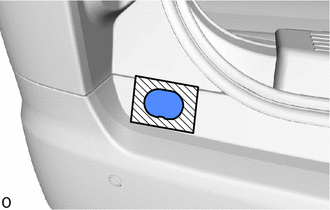

|
Protective Tape |
Apply protective tape around the rear bumper No. 1 plate.
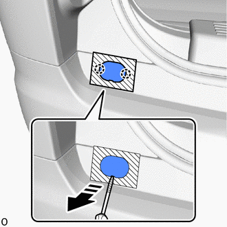

|
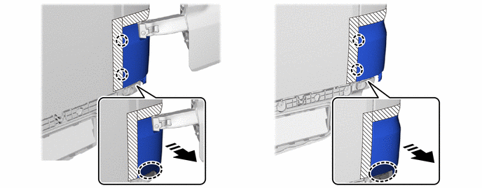
Remove in this Direction |
|
|
Protective Tape |
Using a screwdriver, detach the claw and remove the rear bumper No. 1 plate as shown in the illustration.
- HINT:
-
Tape the screwdriver tip before use.
2.REMOVE REAR BUMPER ASSEMBLY
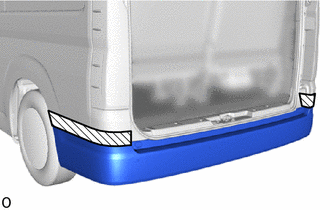
|
|
Protective Tape |
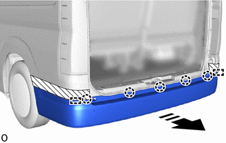
Apply protective tape around the rear bumper assembly.
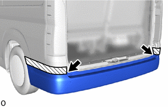
Remove the 2 screws.
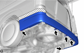
w/o Rear Bumper Lower Cover:
Using a clip remover, remove the 5 clips.
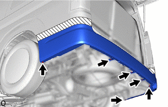
w/ Rear Bumper Lower Cover:
Using a clip remover, remove the 6 clips.
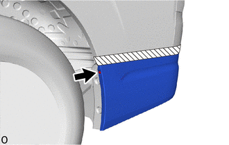
Remove the clip.
- HINT:
-
Use the same procedure for the RH and LH sides.
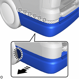

|
Place Hand Here |
|
|
Remove in this Direction |
Place your hand at the position shown in the illustration and detach the claw in the order shown in the illustration.
- HINT:
-
Use the same procedure for the RH and LH sides.
|
|
Remove in this Direction |
Detach the claw and guide and remove the rear bumper assembly as shown in the illustration.
w/ TOYOTA Parking Assist-sensor System:
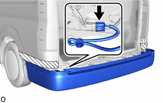
Disconnect the connector.
52166A
3.REMOVE REAR BUMPER UPPER COVER LH
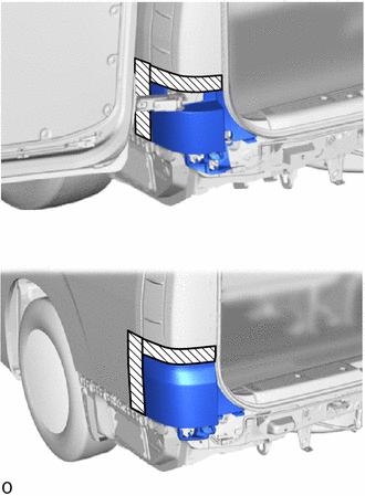
| *A | for Double Swing Out Type |
| *B | except Double Swing Out Type |
|
|
Protective Tape |
Apply protective tape around the rear bumper upper cover LH.
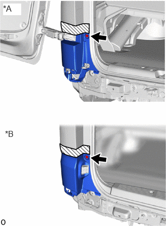
| *A | for Double Swing Out Type |
| *B | except Double Swing Out Type |
Remove the screw.
Place your hand at the positions shown in the illustration and detach the claw.
| *A | for Double Swing Out Type | *B | except Double Swing Out Type |
|
|
Place Hand Here |
|
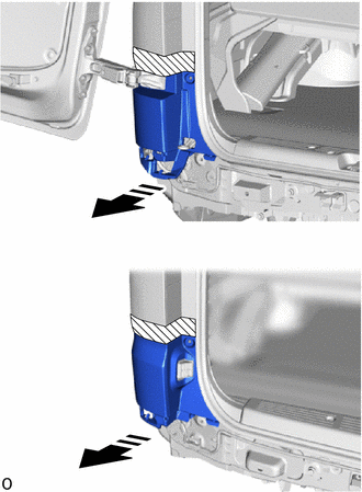
Remove in this Direction |
| *A | for Double Swing Out Type |
| *B | except Double Swing Out Type |
|
|
Remove in this Direction |
Pull toward the rear of the vehicle and remove the rear bumper upper cover LH.
52165A
4.REMOVE REAR BUMPER UPPER COVER RH
- HINT:
-
Use the same procedure for the RH and LH sides.