AUDIO / VIDEO AUDIO AND VISUAL SYSTEM(for Radio and Display Type) Mute Signal Circuit between Radio Receiver and Telematics Transceiver
DESCRIPTION
The telematics transceiver sends a mute signal to the radio and display receiver assembly.
The radio and display receiver assembly controls the volume according to the mute signal from the telematics transceiver.
WIRING DIAGRAM
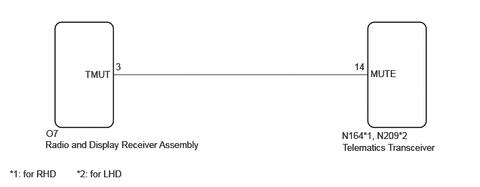
CAUTION / NOTICE / HINT
- NOTICE:
- ·
When replacing the radio and display receiver assembly, always replace it with a new one. If a radio and display receiver assembly which was installed to another vehicle is used, the following may occur:
-A communication malfunction DTC may be stored.
-The radio and display receiver assembly may not operate normally.
·When replacing the telematics transceiver, make sure to replace it with a new one.
- HINT:
-
Depending on the parts that are replaced during vehicle inspection or maintenance, performing initialization, registration or calibration may be needed. Refer to Precaution for Audio and Visual System.
PROCEDURE
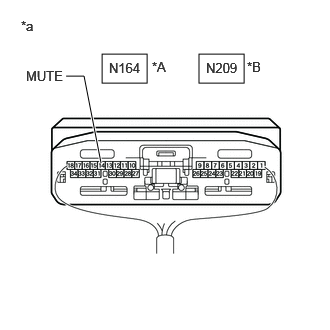
| *A | for RHD |
| *B | for LHD |
| *a | Component with harness connected
(Telematics Transceiver) |
Measure the voltage according to the value(s) in the table below.
- Standard Voltage:
Tester Connection Condition Specified Condition *1: for RHD
*2: for LHD
N164-14 (MUTE) - Body ground*1 Ignition switch ACC
Audio system playing
→ Emergency call mode2.0 V or higher
→ Below 1 VN209-14 (MUTE) - Body ground*2 Ignition switch ACC
Audio system playing
→ Emergency call mode2.0 V or higher
→ Below 1 V
- Result:
Proceed to OK NG
OK
NG
Disconnect the O7 radio and display receiver assembly connector.
Disconnect the N164*1 or N209*2 telematics transceiver connector.
*1: for RHD
*2: for LHD
Measure the resistance according to the value(s) in the table below.
- Standard Resistance:
Tester Connection Condition Specified Condition *1: for RHD
*2: for LHD
O7-3 (TMUT) - N164-14 (MUTE)*1 Always Below 1 Ω O7-3 (TMUT) - N209-14 (MUTE)*2 Always Below 1 Ω O7-3 (TMUT) or N164-14 (MUTE) - Body ground*1 Always 10 kΩ or higher O7-3 (TMUT) or N209-14 (MUTE) - Body ground*2 Always 10 kΩ or higher
- Result:
Proceed to OK NG
OK
NG

| *A | for RHD |
| *B | for LHD |
| *a | Front view of wire harness connector
(to Telematics Transceiver) |
Disconnect the telematics transceiver connector.
Measure the voltage according to the value(s) in the table below.
- Standard Voltage:
Tester Connection Switch Condition Specified Condition *1: for RHD
*2: for LHD
N164-14 (MUTE) - Body ground*1 Ignition switch ACC 2.0 V or higher N209-14 (MUTE) - Body ground*2 Ignition switch ACC 2.0 V or higher
- Result:
Proceed to OK NG
OK
NG