DOOR LOCK POWER DOOR LOCK CONTROL SYSTEM Power Source Circuit
DESCRIPTION
The main power source for the power door lock control system is supplied via the door control battery.
WIRING DIAGRAM
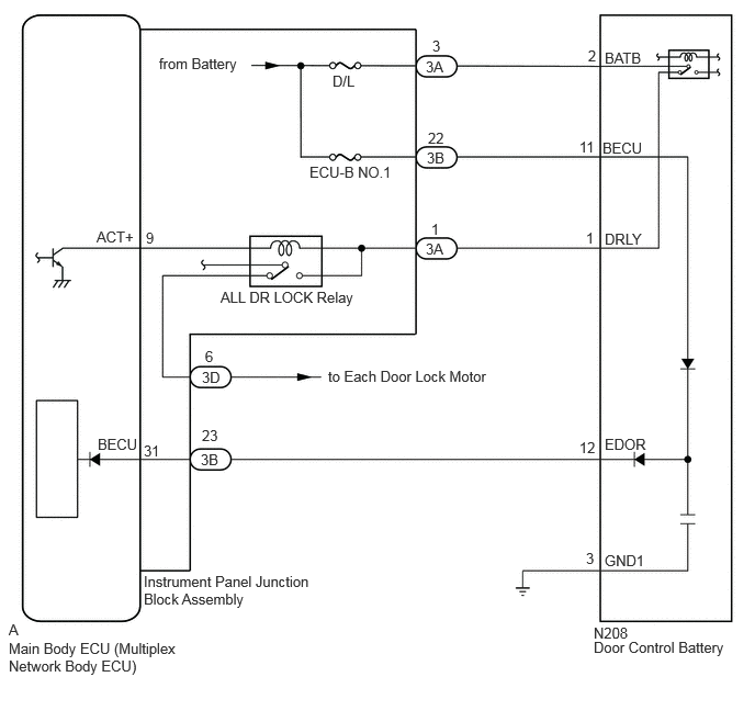
CAUTION / NOTICE / HINT
- NOTICE:
- ·
Before replacing the main body ECU (multiplex network body ECU), refer to the Service Bulletin.*
*: w/ Entry and Start System
·Inspect the fuses for circuits related to this system before performing the following procedure.
·After turning the ignition switch off, waiting time may be required before disconnecting the cable from the negative (-) battery terminal. Therefore, make sure to read the disconnecting the cable from the negative (-) battery terminal notices before proceeding with work.
PROCEDURE
Disconnect the door control battery connector.
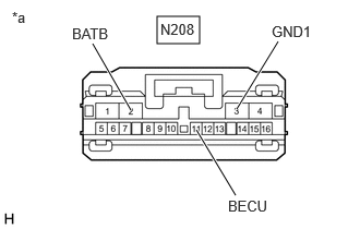
| *a | Front view of wire harness connector
(to Door Control Battery) |
Measure the voltage according to the value(s) in the table below.
- Standard Voltage:
Tester Connection Condition Specified Condition N208-2 (BATB) - Body ground Always 11 to 14 V N208-11 (BECU) - Body ground Always 11 to 14 V
Measure the resistance according to the value(s) in the table below.
- Standard Resistance:
Tester Connection Condition Specified Condition N208-3 (GND1) - Body ground Always Below 1 Ω
- Result:
Result Proceed to OK A NG (GND1 terminal) B NG (Other terminal) C
A
B
C
Check the lighting system operation.
- OK:
Lighting system operates normally.
- Result:
Proceed to OK NG
OK
NG
Disconnect the 3A instrument panel junction block assembly connector.
Disconnect the N208 door control battery connector.
Measure the resistance according to the value(s) in the table below.
- Standard Resistance:
Tester Connection Condition Specified Condition N208-1 (DRLY) - 3A-1 Always Below 1 Ω N208-1 (DRLY) or 3A-1- Other terminals and body ground Always 10 kΩ or higher
- Result:
Proceed to OK NG
OK
NG
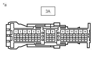
| *a | Front view of wire harness connector
(to Instrument Panel Junction Block Assembly) |
Disconnect the instrument panel junction block assembly connector.
Measure the resistance according to the value(s) in the table below.
- Standard Resistance:
Tester Connection Condition Specified Condition 3A-1 - 3A-3 Always Below 1 Ω 3A-1 or 3A-3- Body ground Always 10 kΩ or higher
- Result:
Proceed to OK NG
OK
NG
Disconnect the 3B instrument panel junction block assembly connector.
Disconnect the N208 door control battery connector.
Measure the resistance according to the value(s) in the table below.
- Standard Resistance:
Tester Connection Condition Specified Condition N208-12 (EDOR) - 3B-23 Always Below 1 Ω N208-12 (EDOR) or 3B-23 - Other terminals and body ground Always 10 kΩ or higher
- Result:
Proceed to OK NG
OK
NG
Remove the instrument panel junction block assembly.
Remove the main body ECU (multiplex network body ECU) from the instrument panel junction block assembly.
Measure the resistance according to the value(s) in the table below.
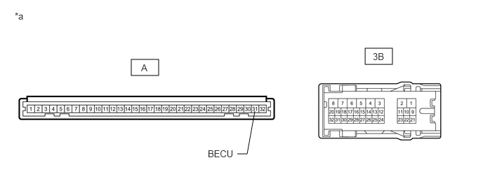
| *a | Component without harness connected
(Instrument Panel Junction Block Assembly) |
- | - |
- Standard Resistance:
Tester Connection Condition Specified Condition A-31 (BECU) - 3B-23 Always Below 1 Ω
- Result:
Proceed to OK NG
OK
NG

| *a | Component with harness connected
(Door Control Battery) |
Turn the ignition switch off.
Leave the vehicle as is for 30 minutes (wait until the door control battery is discharged).
- HINT:
-
Discharge time is reduced when the door control battery is not fully charged.
Measure the voltage according to the value(s) in the table below.
- Standard Voltage:
Tester Connection Condition Specified Condition N208-12 (EDOR) - Body ground Always 11 to 14 V
- Result:
Proceed to OK NG
OK
NG
Disconnect the 3A or 3B instrument panel junction block assembly connector.
Disconnect the N208 door control battery connector.
Measure the resistance according to the value(s) in the table below.
- Standard Resistance:
Tester Connection Condition Specified Condition N208-11 (BECU) - 3B-22 Always Below 1 Ω N208-2 (BATB) - 3A-3 Always Below 1 Ω N208-11 (BECU) or 3B-22 - Other terminals and body ground Always 10 kΩ or higher N208-2 (BATB) or 3A-3 - Other terminals and body ground Always 10 kΩ or higher
- Result:
Proceed to OK NG
OK
NG