NAVIGATION / MULTI INFO DISPLAY NAVIGATION SYSTEM USB Audio System Recognition/Play Error
DESCRIPTION
When a USB device or "iPod" is connected to the USB jack of the No. 1 stereo jack adapter assembly, it must have playable files. The device must also communicate with and be recognized by the radio and display receiver assembly. This diagnostic procedure is for when a device is not recognized, or files from the device cannot be played normally.
WIRING DIAGRAM
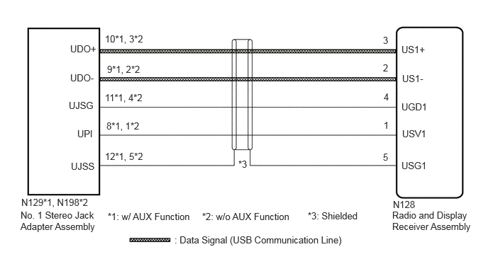
CAUTION / NOTICE / HINT
- NOTICE:
-
When replacing the radio and display receiver assembly, always replace it with a new one. If a radio and display receiver assembly which was installed to another vehicle is used, the following may occur:
- ·
A communication malfunction DTC may be stored.
·The radio and display receiver assembly may not operate normally.
- HINT:
- ·
When a large amount of data is in a USB device, it may take a while to begin playback.
·When using a USB device, files that are protected by copyright cannot be played.
·When files are not played in the sorted order, perform the following procedure before inspection.
(a)Add numbers in front of the file names.
(b)Put the files in a folder and copy the folder data to the USB device.
·Depending on the parts that are replaced during vehicle inspection or maintenance, performing initialization, registration or calibration may be needed. Refer to Precaution for Navigation System.
PROCEDURE
Disconnect the USB device or "iPod" from the No. 1 stereo jack adapter assembly.
Check if playable files are present on the USB device or "iPod".
- HINT:
-
Refer to System Description for playable files.
Check if the USB device is a compatible format or "iPod" is a compatible version.
- HINT:
-
Refer to System Description for compatible formats and versions.
- Result:
Result Proceed to No playable files exist, or incompatible device format or version. A Playable files exist, and compatible device format or version. (w/ AUX Function) B Playable files exist, and compatible device format or version. (w/o AUX Function) C
A
B
C
Disconnect the N128 radio and display receiver assembly connector.
Disconnect the N129 No. 1 stereo jack adapter assembly connector.

| *a | Front view of wire harness connector
(to Radio and Display Receiver Assembly) |
| *b | Front view of wire harness connector
(to No. 1 Stereo Jack Adapter Assembly) |
Measure the resistance according to the value(s) in the table below.
- Standard Resistance:
Tester Connection Condition Specified Condition N128-1 (USV1) - N129-8 (UPI) Always Below 1 Ω N128-2 (US1-) - N129-9 (UDO-) Always Below 1 Ω N128-3 (US1+) - N129-10 (UDO+) Always Below 1 Ω N128-4 (UGD1) - N129-11 (UJSG) Always Below 1 Ω N128-5 (USG1) - N129-12 (UJSS) Always Below 1 Ω N128-1 (USV1) or N129-8 (UPI) - Body ground Always 10 kΩ or higher N128-2 (US1-) or N129-9 (UDO-) - Body ground Always 10 kΩ or higher N128-3 (US1+) or N129-10 (UDO+) - Body ground Always 10 kΩ or higher N128-4 (UGD1) or N129-11 (UJSG) - Body ground Always 10 kΩ or higher N128-5 (USG1) or N129-12 (UJSS) - Body ground Always 10 kΩ or higher
- Result:
Proceed to OK NG
OK
NG
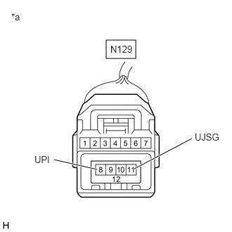
| *a | Front view of wire harness connector
(to No. 1 Stereo Jack Adapter Assembly) |
Disconnect the No. 1 stereo jack adapter assembly connector.
Measure the voltage according to the value(s) in the table below.
- Standard Voltage:
Tester Connection Switch Condition Specified Condition N129-8 (UPI) - N129-11 (UJSG) Ignition switch ACC 5 V
- Result:
Proceed to OK NG
OK
NG
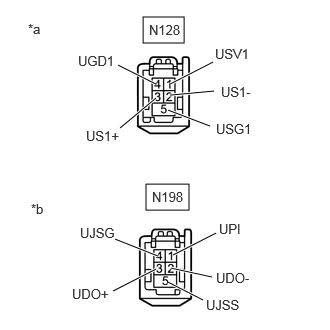
| *a | Front view of wire harness connector
(to Radio and Display Receiver Assembly) |
| *b | Front view of wire harness connector
(to No. 1 Stereo Jack Adapter Assembly) |
Disconnect the radio and display receiver assembly connector.
Disconnect the No. 1 stereo jack adapter assembly connector.
Measure the resistance according to the value(s) in the table below.
- Standard Resistance:
Tester Connection Condition Specified Condition N128-1 (USV1) - N198-1 (UPI) Always Below 1 Ω N128-2 (US1-) - N198-2 (UDO-) Always Below 1 Ω N128-3 (US1+) - N198-3 (UDO+) Always Below 1 Ω N128-4 (UGD1) - N198-4 (UJSG) Always Below 1 Ω N128-5 (USG1) - N198-5 (UJSS) Always Below 1 Ω N128-1 (USV1) - Body ground Always 10 kΩ or higher N128-2 (US1-) - Body ground Always 10 kΩ or higher N128-3 (US1+) - Body ground Always 10 kΩ or higher N128-4 (UGD1) - Body ground Always 10 kΩ or higher N128-5 (USG1) - Body ground Always 10 kΩ or higher
- Result:
Proceed to OK NG
OK
NG
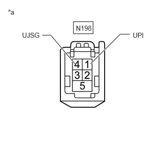
| *a | Front view of wire harness connector
(to No. 1 Stereo Jack Adapter Assembly) |
Disconnect the No. 1 stereo jack adapter assembly connector.
Measure the voltage according to the value(s) in the table below.
- Standard Voltage:
Tester Connection Switch Condition Specified Condition N198-1 (UPI) - N198-4 (UJSG) Ignition switch ACC 5 V
- Result:
Proceed to OK NG
OK
NG
Delete all files in the USB device or "iPod" and format/restore it.
Save the data again and check if it can be played on the in-vehicle device.
- NOTICE:
-
Formatting a USB device or restoring an "iPod" erases all music on the device. Ensure that a backup of the music data is available before performing this operation.
- OK:
Malfunction disappears.
- Result:
Proceed to OK NG
OK
NG
Turn the ignition switch off.
- HINT:
-
When this malfunction occurs, it is necessary to turn the ignition switch off to make it possible for the vehicle to recognize a new device when it is connected.
Turn the ignition switch to ACC.
Connect a known good USB device or "iPod" to the No. 1 stereo jack adapter assembly.
- HINT:
- ·
If the malfunction occurred when a USB device was in use, use another USB device for the inspection. If the malfunction occurred when an "iPod" was in use, use another "iPod" for the inspection.
·Refer to System Description for compatible formats and versions.
- Result:
Proceed to NEXT
NEXT
Check if a USB device or "iPod" is recognized by the radio and display receiver assembly, and if information such as track, artist and album names is displayed on the screen.
- OK:
USB device or "iPod" is recognized properly and the information is displayed on the screen.
- Result:
Proceed to OK NG
OK
NG