CRUISE CONTROL CRUISE CONTROL SYSTEM Steering Pad Switch Circuit
DESCRIPTION
The steering pad switch assembly outputs the on/off signal and various control signals to the ECM.
The ECM performs cruise control according to the signals received from the steering pad switch assembly.
WIRING DIAGRAM
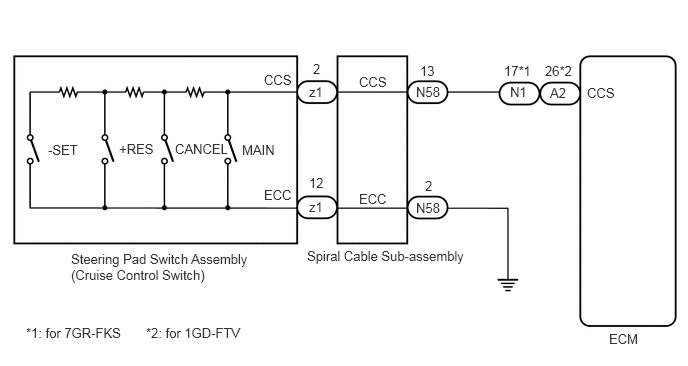
CAUTION / NOTICE / HINT
- NOTICE:
-
The vehicle is equipped with a Supplemental Restraint System (SRS) which includes components such as airbags. Before servicing (including removal or installation of parts), be sure to read the precaution for Supplemental Restraint System.
-
for Type A: Click hereVehicle Interior>SUPPLEMENTAL RESTRAINT SYSTEMS>AIRBAG SYSTEM (for Type A)>PRECAUTION201906,202310,_58,_079257,_0387732,RM100000001IMN3,202310,999999,_58,_079257,_0387732,RM100000002G3KG,
-
for Type B: Click hereVehicle Interior>SUPPLEMENTAL RESTRAINT SYSTEMS>AIRBAG SYSTEM (for Type B)>PRECAUTION201902,202310,_58,_079257,_0385034,RM100000001GJPR,202310,999999,_58,_079257,_0385034,RM100000002G3NC,
PROCEDURE
Connect the GTS to the DLC3.
Turn the ignition switch to ON.
Turn the GTS on.
Enter the following menus: Powertrain / Cruise Control / Data List.
Read the Data List according to the display on the GTS.
except 1GD-FTV (Urea SCR System):
- Powertrain > Cruise Control > Data List
-
Tester Display Measurement Item Range Normal Condition Diagnostic Note Cancel Switch CANCEL switch status ON or OFF ON: CANCEL switch pushed
OFF: CANCEL switch not pushed- -SET Switch -SET switch status ON or OFF ON: -SET switch pushed
OFF: -SET switch not pushed- +RES Switch +RES switch status ON or OFF ON: +RES switch pushed
OFF: +RES switch not pushed- Cruise Main Switch Operation Condition Cruise control main switch status ON or OFF ON: Cruise control main switch pushed
OFF: Cruise control main switch not pushed-
- Powertrain > Cruise Control > Data List
-
Tester Display Cancel Switch -SET Switch +RES Switch Cruise Main Switch Operation Condition - 50003 374 18,19,20,41
for 1GD-FTV (Urea SCR System):
- Powertrain > Cruise Control > Data List
-
Tester Display Measurement Item Range Normal Condition Diagnostic Note Cancel Switch CANCEL switch status ON or OFF ON: CANCEL switch pushed
OFF: CANCEL switch not pushed- -SET Switch -SET switch status ON or OFF ON: -SET switch pushed
OFF: -SET switch not pushed- +RES Switch +RES switch status ON or OFF ON: +RES switch pushed
OFF: +RES switch not pushed- Cruise Main Switch Operation Condition Cruise control main switch status ON or OFF ON: Cruise control main switch pushed
OFF: Cruise control main switch not pushed-
- Powertrain > Cruise Control > Data List
-
Tester Display Cancel Switch -SET Switch +RES Switch Cruise Main Switch Operation Condition - 50003 457 18,19,20,41
- OK:
The value of each measurement item changes according to the operation of the steering pad switch assembly.
- Result:
Proceed to OK NG
OK
NG
Remove the steering pad switch assembly.
Inspect the steering pad switch assembly.
- Result:
Proceed to OK NG
OK
NG
Remove the spiral cable sub-assembly.
Inspect the spiral cable sub-assembly.
- Result:
Proceed to OK NG
OK
NG
Disconnect the N58 spiral cable sub-assembly connector.
for 1GD-FTV:
Disconnect the A2 ECM connector.
for 7GR-FKS:
Disconnect the N1 ECM connector.
Measure the resistance according to the value(s) in the table below.
- Standard Resistance (for 1GD-FTV):
Tester Connection Condition Specified Condition N58-13 (CCS) - A2-26 (CCS) Always Below 1 Ω N58-2 (ECC) - Body ground Always Below 1 Ω N58-13 (CCS) or A2-26 (CCS) - Body ground Always 10 kΩ or higher
- Standard Resistance (for 7GR-FKS):
Tester Connection Condition Specified Condition N58-13 (CCS) - N1-17 (CCS) Always Below 1 Ω N58-2 (ECC) - Body ground Always Below 1 Ω N58-13 (CCS) or N1-17 (CCS) - Body ground Always 10 kΩ or higher
for 1GD-FTV:
Connect the A2 ECM connector.
for 7GR-FKS:
Connect the N1 ECM connector.
Connect the N58 spiral cable sub-assembly connector.
- Result:
Result Proceed to OK (for 1GD-FTV) A OK (for 7GR-FKS) B NG C
A
B
C