POWER OUTLETS (INT) POWER OUTLET SOCKET(for Instrument Panel) INSTALLATION
CAUTION / NOTICE / HINT
- HINT:
- ·
Use the same procedure for RHD and LHD vehicles.
·The procedure listed below is for LHD vehicles.
PROCEDURE

 85535E
1.INSTALL NO. 2 POWER OUTLET SOCKET COVER
85535E
1.INSTALL NO. 2 POWER OUTLET SOCKET COVER
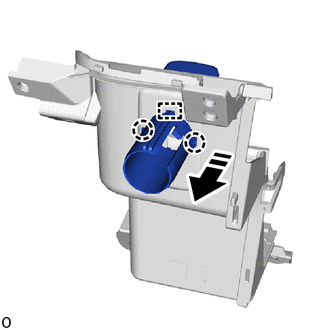

|
Install in this Direction |
Attach the guide and claw to install the No. 2 power outlet socket cover as shown in the illustration.
85530D
2.INSTALL NO. 2 POWER OUTLET SOCKET ASSEMBLY
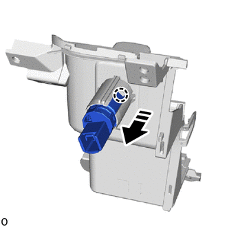
|
|
Install in this Direction |
Attach the claw to install the No. 2 power outlet socket assembly as shown in the illustration.
55620
3.INSTALL INSTRUMENT PANEL CUP HOLDER ASSEMBLY

Attach the claw and guide to install the instrument panel cup holder assembly.
Install the 5 screws.
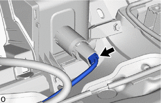
Connect the connector.
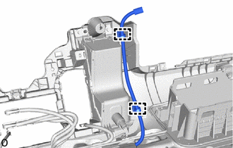
w/ Telematics Transceiver:
Attach the clamp.
55844
4.INSTALL NO. 2 HEATER TO REGISTER DUCT
55845A
5.INSTALL NO. 3 HEATER TO REGISTER DUCT
55990C
6.INSTALL CENTER DEFROSTER NOZZLE ASSEMBLY
7.INSTALL INSTRUMENT PANEL SAFETY PAD
8.CONNECT CABLE TO NEGATIVE BATTERY TERMINAL
9. INITIALIZATION AFTER RECONNECTING BATTERY TERMINAL
- HINT:
-
When disconnecting and reconnecting the battery, there is an automatic learning function that completes learning when the respective system is usel.
10. PERFORM DIAGNOSTIC SYSTEM CHECK
11.CHECK SRS WARNING LIGHT
12.PERFORM SYSTEM INITIALIZATION AND CALIBRATION