7GR-FKS ENGINE MECHANICAL CAMSHAFT REMOVAL
CAUTION / NOTICE / HINT
The necessary procedures (adjustment, calibration, initialization, or registration) that must be performed after parts are removed, installed, or replaced during the camshaft removal/installation are shown below.
| Replaced Part or Performed Procedure | Necessary Procedure | Effect/Inoperative Function when Necessary Procedure not Performed | Link |
|---|---|---|---|
| Battery terminal is disconnected/reconnected | Memorize steering angle neutral point | Parking assist monitor system | ( 201902,999999,_56,_079315,_0385736,RM100000001GNRA,) 201902,999999,_56,_079315,_0385736,RM100000001GNRA,)
|
| Panoramic view monitor system | (201906,999999,_56,_079315,_0396274,RM100000001IGR3,)
|
||
·
Throttle body with motor assembly ·
Cleaning the deposits from the throttle body with motor assembly ·
Camshaft (for intake or exhaust camshaft) ·
Camshaft timing gear assembly ·
Camshaft timing exhaust gear assembly ·
Fuel pump assembly (for high pressure side) ·
Spark plug ·
Ignition coil assembly ·
Air leaks from intake system ·
Gas leaks from exhaust system |
Inspection after repair | ·
Poor idle, etc. ·
Engine start function, etc. |
(201902,999999,_51,_078720,_0381907,RM100000001G2VV,)
|
- HINT:
-
When the cable is disconnected / reconnected to the battery terminal, systems temporarily stop operating. However, each system has a function that completes learning the first time the system is used.
- ·
Learning completes when vehicle is driven
Effect/Inoperative when not Performed Necessary Procedures Link Lane control system Drive the vehicle straight ahead at 15 km/h (10 mph) or more for 1 second or more. ( 201902,999999,_58,_078886,_0382740,RM100000001G6XB,)
Pre-collision system
·Learning completes when vehicle is operated normally
Effect/Inoperative when not Performed Necessary Procedures Link Power slide door system Fully close the slide door by hand.
- HINT:
-
Initialization is not necessary if the above procedures are performed while the slide door is closed.
( 201902,999999,_59,_078503,_0381017,RM100000001FWXM,)
Air conditioning system After the ignition switch is turned to ON, the servo motor standard position is recognized. -
PROCEDURE

 1. PRECAUTION
- NOTICE:
-
After turning the ignition switch is turned off, there may be a waiting time before disconnecting the negative (-) battery terminal.
2.DISCHARGE FUEL SYSTEM PRESSURE
3.DISCONNECT CABLE FROM NEGATIVE BATTERY TERMINAL
53106B
4.REMOVE RADIATOR COVER SUB-ASSEMBLY
51405A
5.REMOVE NO. 1 ENGINE UNDER COVER SUB-ASSEMBLY
6.DRAIN ENGINE OIL
7.DRAIN ENGINE COOLANT
8.DRAIN CLUTCH FLUID (for Manual Transmission)
47220D
9.DISCONNECT BRAKE MASTER CYLINDER RESERVOIR ASSEMBLY
11209
10.REMOVE V-BANK COVER SUB-ASSEMBLY
17751
11.REMOVE NO. 1 AIR CLEANER INLET
17881
12.REMOVE AIR CLEANER ASSEMBLY WITH AIR CLEANER HOSE
44360
13.DISCONNECT VANE PUMP OIL RESERVOIR ASSEMBLY
16470
14.REMOVE RADIATOR RESERVE TANK ASSEMBLY
16571C
15.REMOVE NO. 1 RADIATOR HOSE
16572D
16.REMOVE NO. 2 RADIATOR HOSE
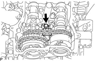
16711
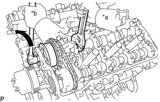
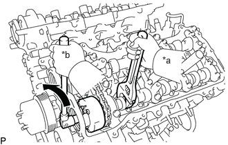
17.REMOVE FAN SHROUD
85110
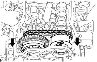
18.REMOVE WINDSHIELD WIPER MOTOR ASSEMBLY
55738D
19.REMOVE NO. 2 HEATER AIR DUCT SPLASH SHIELD SEAL
55701J
20.REMOVE OUTER COWL TOP PANEL SUB-ASSEMBLY
17126
21.REMOVE NO. 2 SURGE TANK STAY
17125
22.REMOVE NO. 1 SURGE TANK STAY
22267A
23.REMOVE THROTTLE BODY BRACKET
17190
24.REMOVE INTAKE AIR SURGE TANK ASSEMBLY
12601B
25.REMOVE NO. 1 ENGINE COVER SUB-ASSEMBLY (w/o Secondary Air Injection System)
12601B
26.REMOVE NO. 1 ENGINE COVER SUB-ASSEMBLY (w/o Secondary Air Injection System)
12261
27.REMOVE PCV HOSE
12262
28.REMOVE NO. 2 PCV HOSE
23901
29.REMOVE FUEL TUBE SUB-ASSEMBLY AND NO. 2 FUEL TUBE SUB-ASSEMBLY
23800
30.REMOVE FUEL DELIVERY WITH SENSOR PIPE ASSEMBLY
17111
31.REMOVE INTAKE MANIFOLD
23903
32.REMOVE NO. 3 FUEL TUBE SUB-ASSEMBLY
23801P
33.REMOVE NO. 1 FUEL PIPE SUB-ASSEMBLY
23100X
34.REMOVE FUEL (ENGINE ROOM SIDE) PUMP ASSEMBLY
17361N
35.REMOVE NO. 1 AIR TUBE (w/ Secondary Air Injection System)
17362
36.REMOVE NO. 2 AIR TUBE (w/ Secondary Air Injection System)
37.REMOVE AIR SWITCHING VALVE ASSEMBLY (w/ Secondary Air Injection System)
17360G
38.REMOVE AIR TUBE ASSEMBLY (w/ Secondary Air Injection System)
82122A
39.DISCONNECT NO. 2 ENGINE WIRE
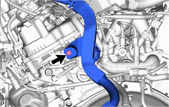
Remove the bolt.
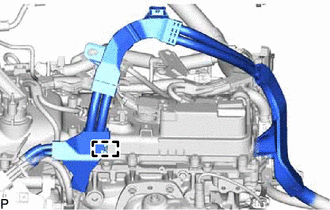
Detach the clamp and disconnect the No. 2 engine wire.
40.DISCONNECT ENGINE WIRE
for Engine LH Side:
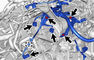
Detach the clamp and disconnect the 3 connectors.
Remove the 3 bolts and disconnect the 3 wire harness clamp brackets.
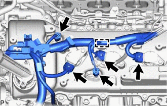
Detach the clamp and disconnect the 5 connectors.
for Engine Rear Side:
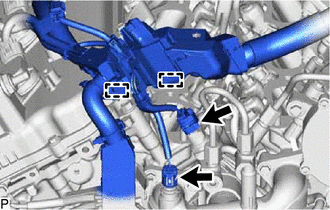
Detach the 2 clamps and disconnect the 2 connectors.
for Engine RH Side:
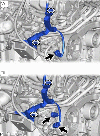
| *A | w/o Variable Flow Control Solenoid Valve |
| *B | w/ Variable Flow Control Solenoid Valve |
w/o Variable Flow Control Solenoid Valve:
Detach the 2 clamps and disconnect the connector.
w/ Variable Flow Control Solenoid Valve:
Detach the 2 clamps and disconnect the 2 connectors.
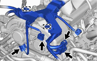
Detach the 2 clamps and disconnect the 4 connectors.
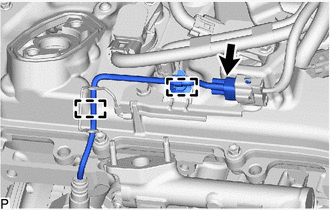
w/ Secondary Air Injection System:
Detach the 2 clamps and disconnect the connector.
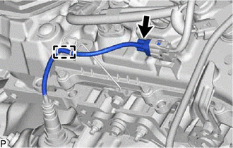
w/o Secondary Air Injection System:
Detach the clamp and disconnect the connector.
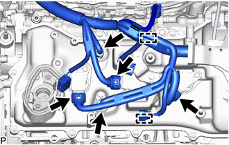
w/ Secondary Air Injection System:
Detach the 2 clamps and disconnect the 5 connectors.
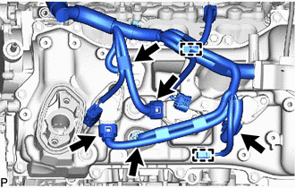
w/o Secondary Air Injection System:
Detach the 2 clamps and disconnect the 5 connectors.
41.REMOVE WIRE HARNESS CLAMP BRACKET
for Cylinder Head Cover Sub-assembly LH Side:
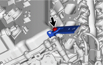
Remove the bolt and wire harness clamp bracket.
for Cylinder Head Cover Sub-assembly Side:
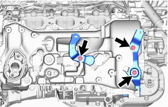
Remove the 3 bolts and 2 wire harness clamp brackets.
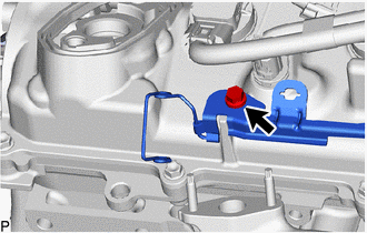
w/ Secondary Air Injection System:
Remove the bolt and wire harness clamp bracket.
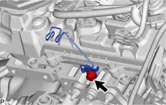
w/o Secondary Air Injection System:
Remove the bolt and wire harness clamp bracket.
19500
42.REMOVE IGNITION COIL ASSEMBLY
11409
43.REMOVE ENGINE OIL LEVEL DIPSTICK GUIDE
15370B
44.REMOVE CAMSHAFT TIMING OIL CONTROL SOLENOID ASSEMBLY (for Intake Side of Bank 1)
15370B
45.REMOVE CAMSHAFT TIMING OIL CONTROL SOLENOID ASSEMBLY (for Exhaust Side of Bank 1)
15370C
46.REMOVE CAMSHAFT TIMING OIL CONTROL SOLENOID ASSEMBLY (for Intake Side of Bank 2)
15370C
47.REMOVE CAMSHAFT TIMING OIL CONTROL SOLENOID ASSEMBLY (for Exhaust Side of Bank 2)
48.REMOVE VVT SENSOR (for Intake Side of Bank 1)
49.REMOVE VVT SENSOR (for Exhaust Side of Bank 1)
50.REMOVE VVT SENSOR (for Intake Side of Bank 2)
51.REMOVE VVT SENSOR (for Exhaust Side of Bank 2)
11202
52.REMOVE CYLINDER HEAD COVER SUB-ASSEMBLY LH
11201
53.REMOVE CYLINDER HEAD COVER SUB-ASSEMBLY
54.DISCONNECT VACUUM HOSE ASSEMBLY
87249B
55.DISCONNECT OUTLET HEATER WATER PIPE B
29300
56.REMOVE VACUUM PUMP ASSEMBLY
11324
57.REMOVE TIMING CHAIN COVER PLATE
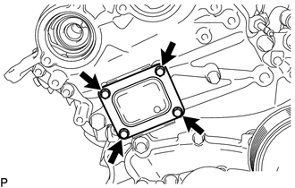
Remove the 4 bolts, timing chain cover plate and gasket.
58.SET NO. 1 CYLINDER TO TDC/COMPRESSION
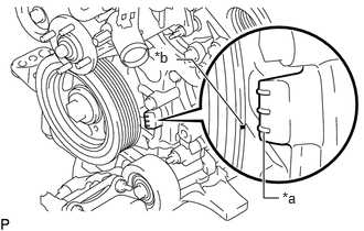
| *a | "0°" Timing Mark |
| *b | Timing Mark (Cutout) |
Turn the crankshaft clockwise to align the timing mark (cutout) on the crankshaft pulley with the "0°" timing mark on the timing chain cover assembly.
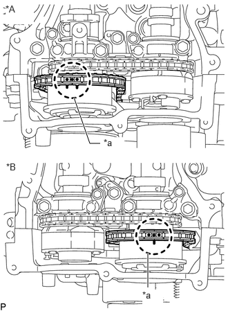
| *A | for Bank 2 |
| *B | for Bank 1 |
| *a | Paint Mark |
Check that the timing marks of the camshaft timing gears are aligned with the timing marks of the bearing caps as shown in the illustration.
- HINT:
-
If the marks are not aligned, turn the crankshaft again to align the marks.
Place paint marks on the timing marks and sprockets of each camshaft timing gear and on the links of the chain.
- HINT:
-
Be sure to place the paint marks on 2 links of the chain and on the sprockets of the camshaft timing gears at the locations of the timing marks of the camshaft timing gears.
13540
59.REMOVE NO. 1 CHAIN TENSIONER ASSEMBLY
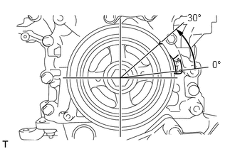
Turn the crankshaft approximately 30° counterclockwise so that there is some slack in the chain.
- HINT:
-
This prevents the valves and pistons from interfering with each other.

| *a | Lever Hole |
| *b | Tensioner Hole |
Align the hole in the lever of the tensioner with the hole in the tensioner body as shown in the illustration, and then insert a pin with a diameter of 1.27 mm (0.0500 in.) into the hole.
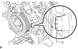
| *a | "0°" Timing Mark |
| *b | Timing Mark (Cutout) |
Turn the crankshaft clockwise to align the timing mark (cutout) on the crankshaft pulley with the "0°" timing mark on the timing chain cover assembly.
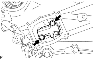
Remove the 2 bolts and No. 1 chain tensioner assembly.
- NOTICE:
-
Do not drop the No. 1 chain tensioner assembly or bolts into the timing chain cover assembly.
13506
60.DISCONNECT CHAIN SUB-ASSEMBLY (for Bank 1)
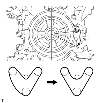
Turn the crankshaft clockwise until it is in the position shown in the illustration so that there is some slack in the chain between the banks.
- CAUTION:
-
As the camshafts turn suddenly, do not touch the camshafts or camshaft timing gears.
- HINT:
-
When turning the crankshaft, engine oil may spray out of the oil holes.
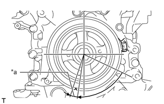
| *a | 5° to 10° |
Turn the crankshaft clockwise until it is in the position shown in the illustration so that the chain can be removed easily.
- HINT:
-
When turning the crankshaft, engine oil may spray out of the oil holes.
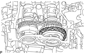
Remove the chain from the sprocket of the camshaft timing gear and set it on the gear.
- CAUTION:
-
As the camshaft may turn suddenly and pinch your fingers when the chain is removed, pinch the chain and lift it upward to remove it from the sprocket.
13550
61.REMOVE NO. 2 CHAIN TENSIONER ASSEMBLY
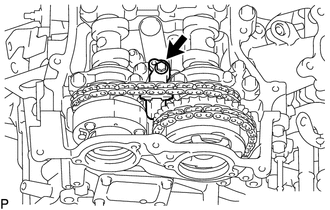
Remove the bolt of the No. 2 chain tensioner assembly.
62.REMOVE CAMSHAFT TIMING GEAR BOLT (for Intake Side of Bank 1)
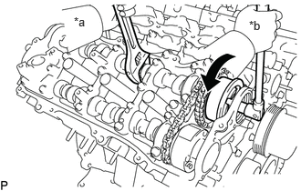
| *a | Hold |
| *b | Turn |
Hold the hexagonal portion of the camshaft with a wrench and remove the camshaft timing gear bolt from the camshaft timing gear assembly.
- NOTICE:
-
Be careful not to damage the camshaft or camshaft housing sub-assembly RH with the wrench.
63.REMOVE CAMSHAFT TIMING GEAR BOLT (for Exhaust Side of Bank 1)
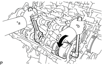
| *a | Hold |
| *b | Turn |
Hold the hexagonal portion of the No. 2 camshaft with a wrench and remove the camshaft timing gear bolt from the camshaft timing exhaust gear assembly.
- NOTICE:
-
Be careful not to damage the No. 2 camshaft or camshaft housing sub-assembly RH with the wrench.
64.REMOVE CAMSHAFT BEARING CAP (for Bank 1)
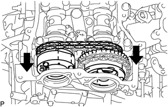
Slide the camshaft timing gear assembly and camshaft timing exhaust gear assembly toward the front of the vehicle.
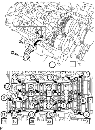
| *a | Replacement Bolt and Washer |
| *b | Part Removal |
| *c | Replacement Bolt and Washer Installation |
Remove the bolts and camshaft bearing caps in the order shown in the illustration. Immediately after removing a bearing cap, install replacement bolts and washers in the order shown in the illustration.
- Torque:
- 28 N*m (286 kgf*cm, 21 ft.*lbf)
- NOTICE:
- ·
Do not install the camshaft bearing caps when installing replacement bolts and washers.
·Be sure to follow the numerical order when performing this procedure.
·Do not allow replacement bolts or washers to contact the camshaft.
·Do not drop replacement bolts or washers into the cylinder head sub-assembly.
- HINT:
- ·
Arrange the removed parts so that they can be reinstalled in their original locations.
·Part number for replacement bolts: 91551-F0850 (8 bolts)
·Part number for replacement washers: 90201-12028 (16 washers)
13512
65.REMOVE NO. 2 CAMSHAFT
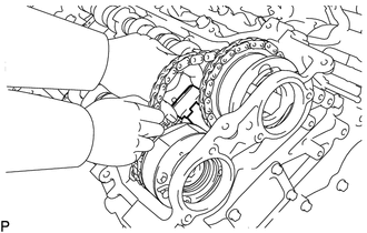
Remove the No. 2 chain tensioner assembly.
Lift up the rear of the No. 2 camshaft so that it is at an angle.
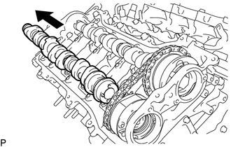
Pull the No. 2 camshaft toward the rear of the vehicle to remove it from the camshaft timing exhaust gear assembly.
13511
66.REMOVE CAMSHAFT
Lift up the rear of the camshaft so that it is at an angle.
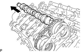
Pull the camshaft toward the rear of the vehicle to remove it from the camshaft timing gear assembly.
13070A
67.REMOVE CAMSHAFT TIMING EXHAUST GEAR ASSEMBLY (for Bank 1)
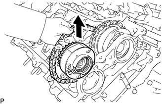
Remove the camshaft timing exhaust gear assembly and No. 2 chain sub-assembly.
13050
68.REMOVE CAMSHAFT TIMING GEAR ASSEMBLY (for Bank 1)
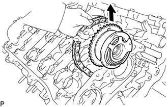
Remove the camshaft timing gear assembly.
- NOTICE:
-
Do not drop the chain sub-assembly into the gap between the engine and cover.
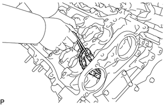
Suspend the chain sub-assembly with a string or equivalent.
13506
69.DISCONNECT CHAIN SUB-ASSEMBLY (for Bank 2)
| *a | "0°" Timing Mark |
| *b | Timing Mark (Cutout) |
Turn the crankshaft clockwise to align the timing mark (cutout) on the crankshaft pulley with the "0°" timing mark on the timing chain cover assembly.
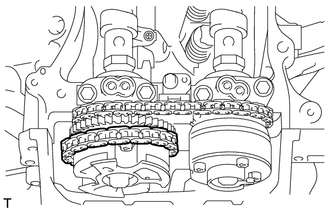
Remove the chain from the sprocket of the camshaft timing gear and set it on the gear.
- CAUTION:
-
As the camshaft may turn suddenly and pinch your fingers when the chain is removed, pinch the chain and lift it upward to remove it from the sprocket.
13560A
70.REMOVE NO. 3 CHAIN TENSIONER ASSEMBLY
Remove the bolt of the No. 3 chain tensioner assembly.
71.REMOVE CAMSHAFT TIMING GEAR BOLT (for Intake Side of Bank 2)
| *a | Hold |
| *b | Turn |
Hold the hexagonal portion of the No. 3 camshaft sub-assembly with a wrench and remove the camshaft timing gear bolt from the camshaft timing gear assembly.
- NOTICE:
-
Be careful not to damage the No. 3 camshaft sub-assembly or camshaft housing sub-assembly LH with the wrench.
72.REMOVE CAMSHAFT TIMING GEAR BOLT (for Exhaust Side of Bank 2)
| *a | Hold |
| *b | Turn |
Hold the hexagonal portion of the No. 4 camshaft sub-assembly with a wrench and remove the camshaft timing gear bolt from the camshaft timing exhaust gear assembly.
- NOTICE:
-
Be careful not to damage the No. 4 camshaft sub-assembly or camshaft housing sub-assembly LH with the wrench.
73.REMOVE CAMSHAFT BEARING CAP (for Bank 2)
Slide the camshaft timing gear assembly and camshaft timing exhaust gear assembly toward the front of the vehicle.
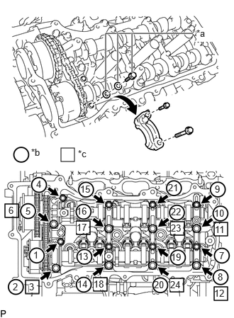
| *a | Replacement Bolt and Washer |
| *b | Part Removal |
| *c | Replacement Bolt and Washer Installation |
Remove the bolts and camshaft bearing caps in the order shown in the illustration. Immediately after removing a bearing cap, install replacement bolts and washers in the order shown in the illustration.
- Torque:
- 28 N*m (286 kgf*cm, 21 ft.*lbf)
- NOTICE:
- ·
Do not install the camshaft bearing caps when installing replacement bolts and washers.
·Be sure to follow the numerical order when performing this procedure.
·Do not allow replacement bolts or washers to contact the camshaft.
·Do not drop replacement bolts or washers into the cylinder head.
- HINT:
- ·
Arrange the removed parts so that they can be reinstalled in their original locations.
·Part number for replacement bolts: 91551-F0850 (8 bolts)
·Part number for replacement washers: 90201-12028 (16 washers)
13054
74.REMOVE NO. 4 CAMSHAFT SUB-ASSEMBLY
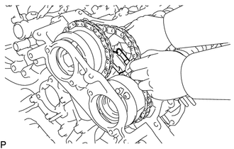
Remove the No. 3 chain tensioner assembly.
Lift up the rear of the No. 4 camshaft sub-assembly so that it is at an angle.
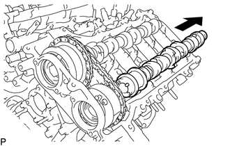
Pull the No. 4 camshaft toward the rear of the vehicle to remove it from the camshaft timing exhaust gear assembly.
13053
75.REMOVE NO. 3 CAMSHAFT SUB-ASSEMBLY
Lift up the rear of the camshaft so that it is at an angle.
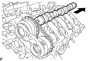
Pull the No. 3 camshaft sub-assembly toward the rear of the vehicle to remove it from the camshaft timing gear assembly.
13070A
76.REMOVE CAMSHAFT TIMING EXHAUST GEAR ASSEMBLY (for Bank 2)
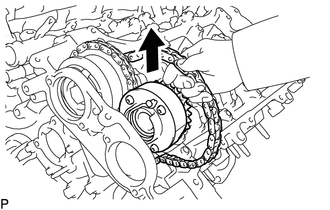
Remove the camshaft timing exhaust gear assembly and No. 2 chain sub-assembly.
13050
77.REMOVE CAMSHAFT TIMING GEAR ASSEMBLY (for Bank 2)
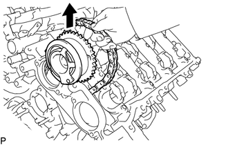
Remove the camshaft timing gear assembly.
- NOTICE:
-
Do not drop the chain sub-assembly into the gap between the engine and cover.
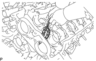
Suspend the chain sub-assembly with a string or equivalent.