LIGHTING (INT) LIGHTING SYSTEM Ambient Illumination Light Circuit
DESCRIPTION
The main body ECU (multiplex network body ECU) controls the operation of the following lights:
No. 1 interior illumination light assembly (slide door illumination)
No. 2 interior illumination light assembly (slide door illumination)
No. 1 interior illumination light assembly (quarter trim illumination)
No. 2 interior illumination light assembly (quarter trim illumination)
WIRING DIAGRAM
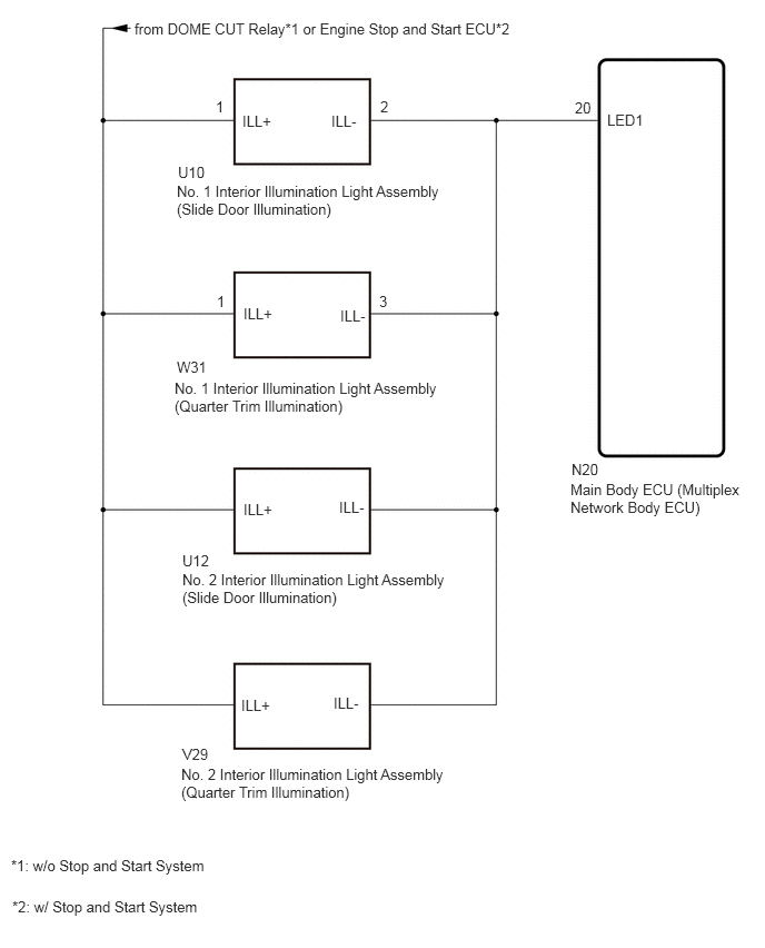
CAUTION / NOTICE / HINT
- NOTICE:
-
Before replacing the main body ECU (multiplex network body ECU), refer to Service Bulletin.
PROCEDURE
Perform the Active Test according to the display on the GTS.
- Body Electrical > Main Body > Active Test
-
Tester Display Measurement Item Control Range Diagnostic Note Interior Illumination Light1 Illuminates the following lights:
·No. 1 interior illumination light assembly (Slide Door Illumination)
·No. 2 interior illumination light assembly (Slide Door Illumination)
·No. 1 interior illumination light assembly (Quarter Trim Illumination)
·No. 2 interior illumination light assembly (Quarter Trim Illumination)
OFF or ON -
- Body Electrical > Main Body > Active Test
-
Tester Display Interior Illumination Light1 - 50004 123 68
- OK:
No. 1 interior illumination light assembly (slide door illumination), No. 2 interior illumination light assembly (slide door illumination), No. 1 interior illumination light assembly (quarter trim illumination) and No. 2 interior illumination light assembly (quarter trim illumination) are illuminate.
- Result:
Proceed to OK NG
OK
NG
Disconnect the U10 No. 1 interior illumination light assembly (slide door illumination) connector.
Disconnect the U12 No. 2 interior illumination light assembly (slide door illumination) connector.
Disconnect the W31 No. 1 interior illumination light assembly (quarter trim illumination) connector.
Disconnect the V29 No. 2 interior illumination light assembly (quarter trim illumination) connector.
Disconnect the N20 main body ECU (multiplex network body ECU) connector.
Measure the voltage according to the value(s) in the table below.
- Standard Voltage:
w/ Stop and Start System Tester Connection Condition Specified Condition U10-1 (ILL+) - Body ground Always 10.5 to 16 V
w/o Stop and Start System Tester Connection Condition Specified Condition U10-1 (ILL+) - Body ground DOME CUT relay off 11 to 14 V
Measure the resistance according to the value(s) in the table below.
- Standard Resistance:
Tester Connection Condition Specified Condition U10-2 (ILL-) - N20-20 (LED1) Always Below 1 Ω
- Result:
Result Proceed to OK (for LHD) A OK (for RHD) B NG C
A
B
C