CRUISE CONTROL DYNAMIC RADAR CRUISE CONTROL SYSTEM Steering Pad Switch Circuit
DESCRIPTION
The steering pad switch assembly outputs the dynamic cruise control on/off signal and various control signals to the ECM.
The ECM controls the dynamic cruise control system according to the signals received from the steering pad switch assembly.
WIRING DIAGRAM
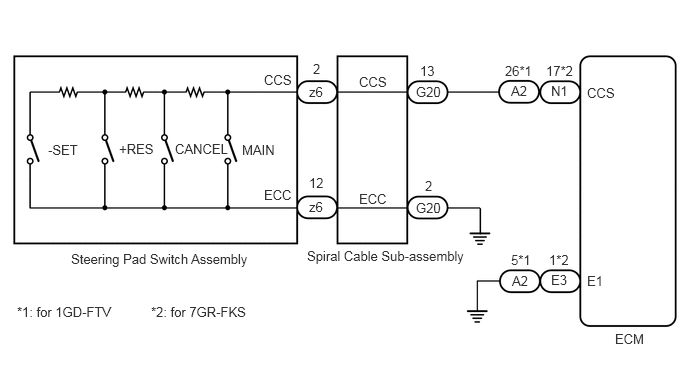
CAUTION / NOTICE / HINT
- NOTICE:
- ·
Before replacing the ECM, refer to Service Bulletin.
·The vehicle is equipped with a Supplemental Restraint System (SRS) which includes components such as airbags. Before servicing (including removal or installation of parts), be sure to read the precaution for Supplemental Restraint System.
for Type A: Click hereVehicle Interior>SUPPLEMENTAL RESTRAINT SYSTEMS>AIRBAG SYSTEM (for Type A)>PRECAUTION201906,202310,_58,_079257,_0387732,RM100000001IMN3,202310,999999,_58,_079257,_0387732,RM100000002G3KG,
for Type B: Click hereVehicle Interior>SUPPLEMENTAL RESTRAINT SYSTEMS>AIRBAG SYSTEM (for Type B)>PRECAUTION201902,202310,_58,_079257,_0385034,RM100000001GJPR,202310,999999,_58,_079257,_0385034,RM100000002G3NC,
PROCEDURE
Connect the GTS to the DLC3.
Turn the engine switch on (IG).
Turn the GTS on.
Enter the following menus: Powertrain / Radar Cruise1 / Data List.
Read the Data List according to the display on the GTS.
- Powertrain > Cruise Control > Data List
-
Tester Display Measurement Item Range Normal Condition Diagnostic Note Cancel Switch CANCEL switch status ON or OFF ON: CANCEL switch pushed
OFF: CANCEL switch not pushed- -SET Switch -SET switch status ON or OFF ON: -SET switch pushed
OFF: -SET switch not pushed- +RES Switch +RES switch status ON or OFF ON: +RES switch pushed
OFF: +RES switch not pushed- Cruise Main Switch Operation Condition Cruise control main switch status ON or OFF ON: Cruise control main switch pushed
OFF: Cruise control main switch not pushed-
- Powertrain > Cruise Control > Data List
-
Tester Display Cancel Switch -SET Switch +RES Switch Cruise Main Switch Operation Condition - 50003 374 18,19,20,41
- OK:
The value of each Data List item changes according to the operation of the steering pad switch assembly.
- Result:
Proceed to OK NG
OK
NG
Remove the steering pad switch assembly.
Inspect the steering pad switch assembly.
- Result:
Proceed to OK NG
OK
NG
Remove the spiral cable sub-assembly.
Inspect the spiral cable sub-assembly.
- Result:
Proceed to OK NG
OK
NG
for 1GD-FTV:
Disconnect the N58 spiral cable sub-assembly connector.
Disconnect the A2 ECM connector.
Measure the resistance according to the value(s) in the table below.
- Standard Resistance:
Tester Connection Condition Specified Condition A2-2 (CCS) - N58-13 (CCS) Always Below 1 Ω A2-26 (CCS) or N58-13 (CCS) - Body ground Always 10 kΩ or higher N58-2 (ECC) - Body ground Always 10 kΩ or higher
Connect the A2 ECM connector.
Connect the N58 spiral cable sub-assembly connector.
for 7GR-FKS:
Disconnect the N58 spiral cable sub-assembly connector.
Disconnect the N1 ECM connector.
Measure the resistance according to the value(s) in the table below.
- Standard Resistance:
Tester Connection Condition Specified Condition N1-17 (CCS) - N58-13 (CCS) Always Below 1 Ω N1-17 (CCS) or N58-13 (CCS) - Body ground Always 10 kΩ or higher N58-2 (ECC) - Body ground Always 10 kΩ or higher
Connect the N1 ECM connector.
Connect the N58 spiral cable sub-assembly connector.
- Result:
Proceed to OK NG
OK
NG
for 1GD-FTV:
Disconnect the A2 ECM connector.
Measure the resistance according to the value(s) in the table below.
- Standard Resistance:
Tester Connection Condition Specified Condition A2-5 (E1) - Body ground Always Below 1 Ω
Connect the A2 ECM connector.
for 7GR-FKS:
Disconnect the E3 ECM connector.
Measure the resistance according to the value(s) in the table below.
- Standard Resistance:
Tester Connection Condition Specified Condition E3-1 (E1) - Body ground Always Below 1 Ω
Connect the E3 ECM connector.
- Result:
Proceed to OK NG
OK
for 7GR-FKS: Click hereEngine / Hybrid System>7GR-FKS (ENGINE CONTROL)>ECM>REMOVAL201906,202310,_51,_078720,_0381918,RM100000001IOND,202310,999999,_51,_078720,_0381918,RM100000002G3CO,
NG