DOOR / HATCH SLIDE DOOR(for Wagon) REASSEMBLY
CAUTION / NOTICE / HINT
- HINT:
- ·
Use the same procedure for RHD and LHD vehicles.
·The procedure listed below is for LHD vehicles.
·Use the same procedure for the RH and LH sides.
·Use the same procedure described for the RH side.
·A bolt without a torque specification is shown in the standard bolt chart.
PROCEDURE

 1.INSTALL CUSHION
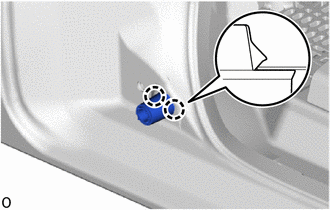
Attach the claw and install the cushion.
69485D
2.INSTALL SLIDE DOOR OPEN STRIKER RH
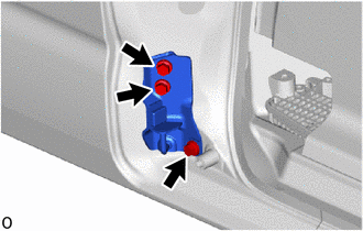
Install the slide door open striker RH with the 3 bolts.
- Torque:
- 27.5 N*m (280 kgf*cm, 20 ft.*lbf)
69416B
3.INSTALL SLIDE DOOR DOWN MALE STOPPER
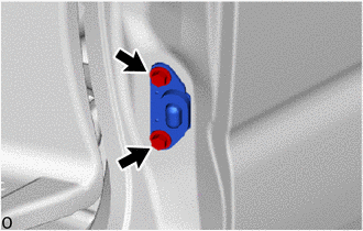
Temporarily install the slide door down male stopper with the 2 bolts.
- HINT:
-
When installing the slide door down female stopper, install the slide door down male stopper.
67155C
4.INSTALL REAR DOOR CORNER BRACKET RH (w/ Rear Seat)
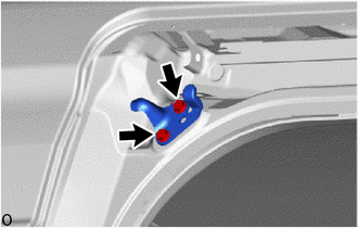
Install the rear door corner bracket RH with the 2 bolts.
- Torque:
- 7.5 N*m (76 kgf*cm, 66 in.*lbf)
69418L
5.INSTALL SLIDE DOOR OPEN STOP RH
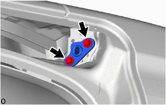
Temporarily install the slide door open stop RH with the 2 bolts.
- HINT:
-
When installing the slide door upper roller assembly RH, install the slide door open stop RH.
68335C
6.INSTALL SLIDE DOOR LOWER ROLLER ARM RH
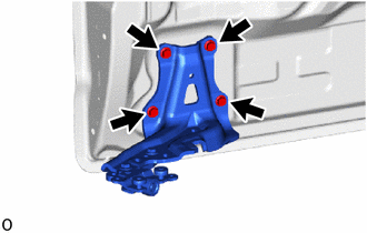
Install the slide door lower roller assembly RH with the 4 bolts.
- Torque:
- 19.5 N*m (199 kgf*cm, 14 ft.*lbf)
68301C
7.INSTALL SLIDE DOOR UPPER ROLLER ASSEMBLY RH
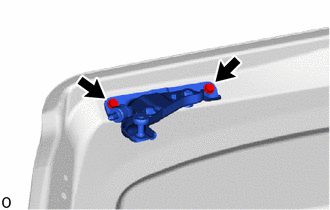
Temporarily install the slide door upper roller assembly RH with the 2 bolts.
Fully close the rear door panel sub-assembly RH.
Tighten the 2 bolts and install the slide door open stop RH.
- Torque:
- 7.5 N*m (76 kgf*cm, 66 in.*lbf)
Tighten the 2 bolts and install the slide door upper roller assembly RH.
- Torque:
- 11.5 N*m (117 kgf*cm, 8 ft.*lbf)
68380D
8.INSTALL SLIDE DOOR CENTER HINGE ASSEMBLY RH
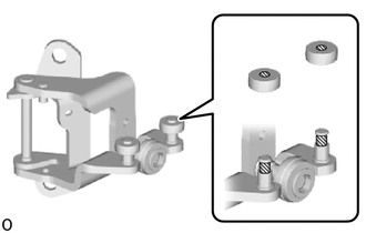

|
MP grease |
Apply MP grease between the pin and roller as shown in the illustration.
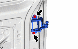
Install the slide door center hinge assembly RH with the 2 bolts.
- Torque:
- 19.5 N*m (199 kgf*cm, 14 ft.*lbf)
67003
9.INSTALL REAR DOOR PANEL SUB-ASSEMBLY RH
|
|
MP Grease |
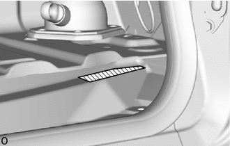
Apply MP grease to the lower slide door rail RH as shown in the illustration.
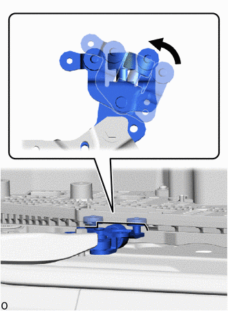
| *a | Cutout |
Rotate the roller part of the slide door lower roller arm sub-assembly RH counterclockwise to connect the slide door lower roller arm sub-assembly RH to the cutout of the slide door motor unit RH.
- NOTICE:
- ·
Support the lower portion of the slide door RH when connecting the slide door lower roller arm sub-assembly RH, as the slide door RH becomes unstable.
·Work with 2 or more persons when connecting the slide door RH in order to prevent deformation and damage.
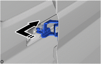

|
Install in this Direction |
Install the slide door center hinge assembly RH from the rear part of the center slide door rail RH.
|
|
Install in this Direction |
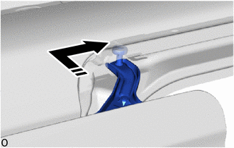
Install the roller part of the slide door upper roller assembly RH from the rear part of the upper slide door rail RH, and then install the slide door RH as shown in the illustration.
w/ Power Slide Door:
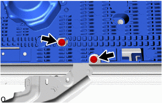
Move the slide door RH so that the 2 bolts are visible as shown in the illustration.
Connect the slide door lower roller assembly RH to the slide door motor unit RH with the 2 bolts.
- Torque:
- 7.8 N*m (80 kgf*cm, 69 in.*lbf)
|
|
Install in this Direction |
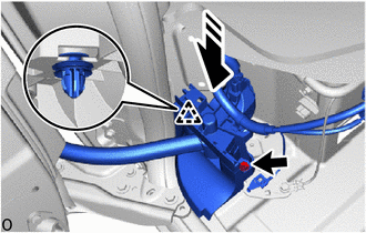
Install the wire harness protector.
Attach the clip as shown in the illustration.
Install the wire harness protector with the bolt.
- Torque:
- 13 N*m (133 kgf*cm, 10 ft.*lbf)

|
Ground Bolt |

|
Connector |
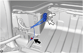
Connect the wire harness (w/o Power Slide Door).
Connect the 2 connectors.
Install the ground wire with the ground bolt.
- Torque:
- 10 N*m (102 kgf*cm, 7 ft.*lbf)
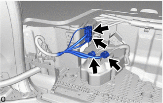
Connect the wire harness (w/ Power Slide Door).
Connect the 4 connectors.
68325
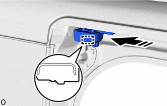
10.INSTALL SLIDE DOOR UPPER RAIL CUSHION RH
|
|
Install in this Direction |
Attach the guide and install the slide door upper rail cushion RH as shown in the illustration.
67887D
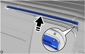
11.INSTALL NO. 2 SLIDE DOOR WEATHERSTRIP RH
Remove any non-drying sealer on the body with non-residue solvent.
| *a | Matchmark |
|
|
Install in this Direction |
Align the matchmark on the body side with the matchmark on a new No. 2 slide door weatherstrip RH and install the No. 2 slide door weatherstrip RH as shown in the illustration.
- NOTICE:
-
When installing, make sure that non-drying sealer does not adhere to the body and slide door.
- HINT:
-
 1.729,1.063 2.865,0.865 true 2.906,0.75 3.313,1.094 0.406,0.344 10 false *a
*a Vehicle Body
-
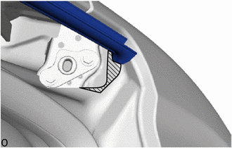
Check that the No. 2 slide door weatherstrip RH contacts the body surface.
68073
12.INSTALL SLIDE RAIL END MOULDING SUB-ASSEMBLY RH
| *a | Clip (part a) |
|
|
Install in this Direction (1) |

|
Install in this Direction (2) |
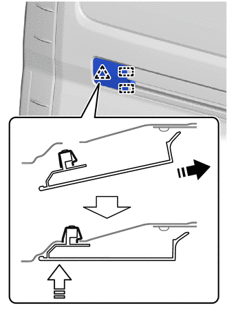
Slide the slide rail end moulding sub-assembly RH in the direction (1) indicated by the arrow shown in the illustration and attach the guide.
Push the clip (part a) in the direction (2) indicated by the arrow shown in the illustration and install the slide rail end moulding sub-assembly RH.
51078D
13.INSTALL SIDE STEP BRACKET SUB-ASSEMBLY RH
68394A
14.INSTALL SLIDE DOOR LOWER RAIL PLATE RH (w/o Power Slide Door)
68394A
15.INSTALL SLIDE DOOR LOWER RAIL PLATE RH (w/ Power Slide Door)
67917C
16.INSTALL REAR DOOR SCUFF PLATE RH
67897M
17.INSTALL NO. 4 SLIDE DOOR WEATHERSTRIP RH

Attach the clip and install the No. 4 slide door weatherstrip RH in the order shown in the illustration.
67837C
18.INSTALL REAR DOOR DUST PROOF SEAL
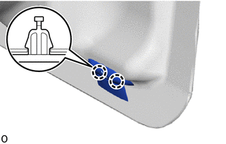
Attach the claw and install the rear door dust proof seal.
- HINT:
-
Use the same procedure described for the other side.
19.INSTALL CUSHION
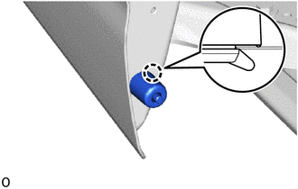
Attach the claw and install the cushion.
- HINT:
-
Use the same procedure described for the other side.
69425C
20.INSTALL SLIDE DOOR STOP CUSHION (w/o Power Slide Door)
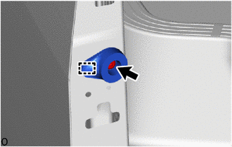
Attach the guide.
Using a T30 "TORX" socket wrench, install the slide door stop cushion with the "TORX" screw.
- Torque:
- 7.5 N*m (76 kgf*cm, 66 in.*lbf)
67785D
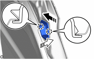
21.INSTALL REAR DOOR UPPER TRIM COVER RH (w/ Rear Seat)
|
|
Install in this Direction (1) |
|
|
Install in this Direction (2) |
Attach the claw and install the rear door upper trim cover RH as shown in the illustration.
67161B
22.INSTALL SLIDE DOOR UPPER INSIDE PANEL EXTENSION RH (w/ Rear Seat)
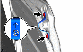
Install slide door upper inside panel extension RH with the 2 bolts in the order shown in the illustration.
- Torque:
- 7.5 N*m (76 kgf*cm, 66 in.*lbf)
- HINT:
-
Install the slide door upper inside panel extension RH so that the arrow mark faces the top of the vehicle as shown in the illustration.
69415
23.CONNECT SLIDE DOOR DOWN FEMALE STOPPER
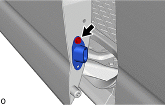
Connect the slide door down female stopper with the bolt.
84250B
24.INSTALL POWER SLIDE DOOR SENSOR ASSEMBLY RH (w/ Power Slide Door)
67865D
25.INSTALL CENTER PILLAR UPPER END WEATHERSTRIP RH (w/o Power Slide Door)
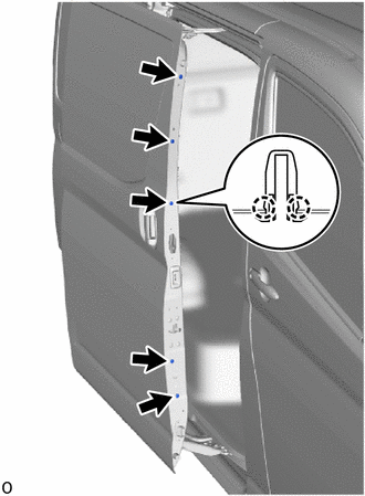
Attach the claw and install the 5 screw grommets.
When using a new center pillar upper end wetherstrip RH:
Remove the release paper from the center pillar upper end wetherstrip RH.
- HINT:
-
After removing the release paper, keep the exposed adhesive free from foreign matter.
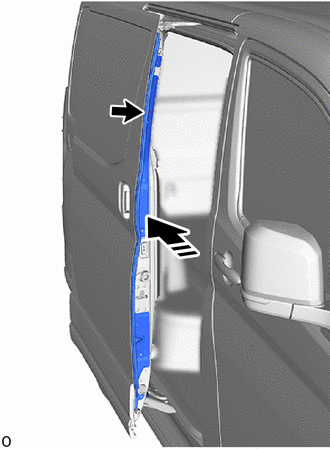
|
|
Install in this Direction |
Temporarily install the center pillar upper end weatherstrip RH with the temporary screw.
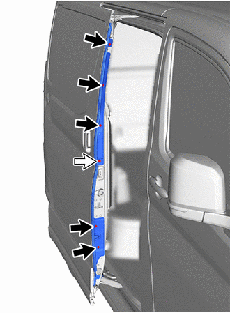
|
|
Screw |
|
|
Bolt |
Install the center pillar upper end weatherstrip RH with the bolt and 5 screws.
- Torque:
- Bolt : 7.5 N*m (76 kgf*cm, 66 in.*lbf)
69415
26.INSTALL SLIDE DOOR DOWN FEMALE STOPPER
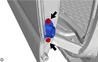
Temporarily install the slide door down female stopper with the 2 bolts.
Fully close the slide door panel sub-assembly RH.
Tighten the 2 bolts and install the slide door down female stopper.
- Torque:
- 7.5 N*m (76 kgf*cm, 66 in.*lbf)
Tighten the 2 bolts and install the slide door down male stopper.
- Torque:
- 7.5 N*m (76 kgf*cm, 66 in.*lbf)
89831F
27.INSTALL NO. 3 SIDE AIRBAG SENSOR (w/ Rear Curtain Shield Airbag)
86160B
28.INSTALL REAR SPEAKER ASSEMBLY
69630C
29.INSTALL SLIDE DOOR LOCK REMOTE CONTROL ASSEMBLY RH
Apply MP grease to the sliding parts of the slide door lock remote control assembly RH.
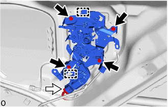
|
|
Bolt |
|
|
Connector |
Attach the guide and install the slide door lock remote control assembly RH with the 4 bolts.
- Torque:
- 7.5 N*m (76 kgf*cm, 66 in.*lbf)
Connect the each connector.
69330E
30.INSTALL SLIDE DOOR LOCK ASSEMBLY RH (w/o Power Slide Door)
69200
31.INSTALL POWER SLIDE DOOR LOCK ASSEMBLY RH (w/ Power Slide Door)
69370B
32.INSTALL SLIDE DOOR FRONT LOCK ASSEMBLY RH
69730A
33.INSTALL REAR DOOR LOCK CONTROL LINK ASSEMBLY RH (w/ Cover)
69230
34.INSTALL REAR DOOR OUTSIDE HANDLE ASSEMBLY RH
Apply MP grease to the sliding part of the rear door outside handle assembly RH.
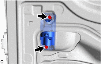
Install the rear door outside handle assembly RH with the 2 bolts.
- Torque:
- 5.5 N*m (56 kgf*cm, 49 in.*lbf)
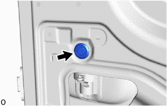
Install the hole plug.
69713A
35.INSTALL REAR DOOR LOCK REMOTE CONTROL LINK RH
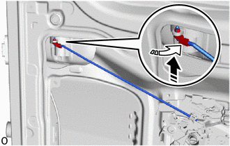
|
|
Install in this Direction (1) |
|
|
Install in this Direction (2) |
Connect the rear door lock remote control link RH in the direction indicated by the arrow (1) as shown in the illustration.
Attach the snap in the direction indicated by the arrow (2) as shown in the illustration.
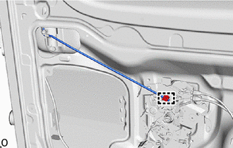
Attach the clamp and install the rear door lock remove control link RH.
When using a new rear door outside handle assembly RH:
Remove the protective tape from the rear door outside handle assembly RH.
69070
36.INSTALL SLIDE DOOR HANDLE ASSEMBLY RH
Apply MP grease to the sliding part of the slide door handle assembly RH.
Detach the clamp.
Straighten each cable, position them as shown in the illustration and install them with each clamp.
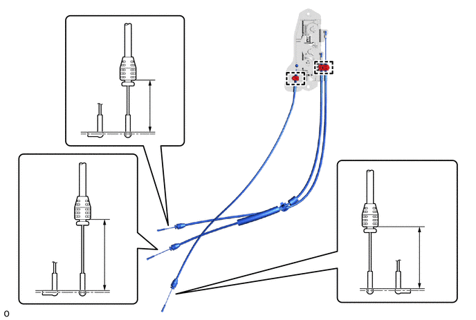
| *a | Locking Cable (Orange) | *b | Close Cable (Purple) |
| *c | Open Cable (Blue) | - | - |
- Standard:
Area Standard Dimension Area Standard Dimension A 59.6 to 61.2 mm (2.35 to 2.41 in.) B 57.7 to 59.3 mm (2.27 to 2.34 in.) C 41.35 to 42.75 mm (1.63 to 1.68 in.) - -
Attach the clamp.
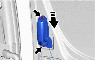
|
|
Install in this Direction |
Insert each cable into the service hole and install the slide door handle assembly RH with the 2 bolts.
- Torque:
- 7.5 N*m (76 kgf*cm, 66 in.*lbf)
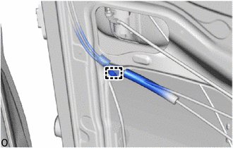
Attach the clamp.
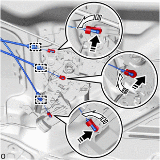
| *a | Locking Cable (Orange) |
| *b | Open Cable (Blue) |
| *c | Close Cable (Purple) |
|
|
Install in this Direction (1) |
|
|
Install in this Direction (2) |
Attach the 3 snaps and connect the 3 cables to the slide door lock remote control assembly RH as shown in the illustration.
Attach the clamp.
69050
37.INSTALL SLIDE DOOR FULL OPEN STOP LOCK ASSEMBLY RH
Apply MP grease to the sliding part of the slide door full open stop lock assembly RH.
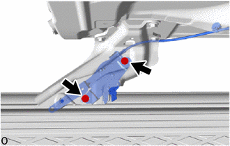
Install the slide door full open stop lock assembly RH with the 2 bolts.
- Torque:
- 5.5 N*m (56 kgf*cm, 49 in.*lbf)
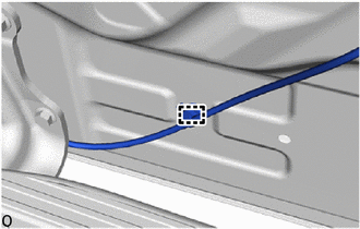
Attach the clamp.
85975A
38.INSTALL SLIDE DOOR CLOSER RELAY (w/o Power Slide Door)
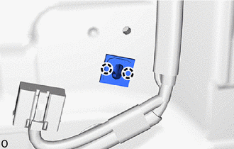
Attach the claw and install the clip.
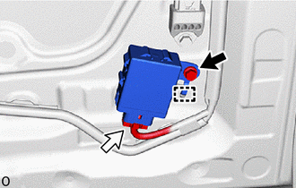
|
|
Bolt |
|
|
Connector |
Connect the connector.
Attach the guide and install the slide door closer relay with the bolt.
- NOTICE:
-
Do not reuse a slide door closer relay that has been subjected to an impact or dropped.
67851E
39.INSTALL SLIDE DOOR SERVICE HOLE COVER RH
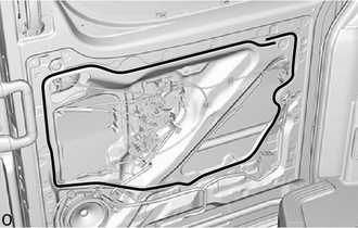

|
Butyl tape |
Apply new butyl tape to the slide door panel.
- HINT:
- ·
Begin applying the butyl tape from the reference point shown in the illustration.
·The butyl tape can be applied from either reference point.
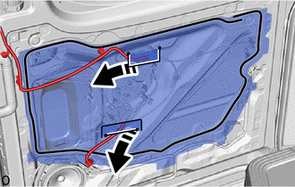
|
|
Install in this Direction |
Pass the rear door wire RH through a new slide door service hole cover RH.
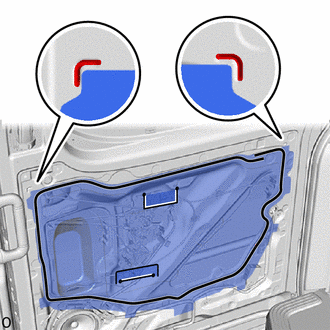
| *a | Reference Point |
Align the top of the slide door service hole cover RH with the reference point on the slide door panel and install it.
- NOTICE:
- ·
Securely install the slide door service hole cover RH to prevent wrinkles and air bubbles.
·There should be no wrinkles or folds after installing the slide door service hole cover RH.
·After installing the slide door service hole cover RH, check the seal quality.

Attach the clamp and install the 2 cable clamps.
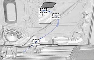
Connect the cable to the cable clamp.
Fold back the slide door service hole cover RH, attach the clamp and connect the slide door full open lock sub-assembly cable as shown in the illustration.
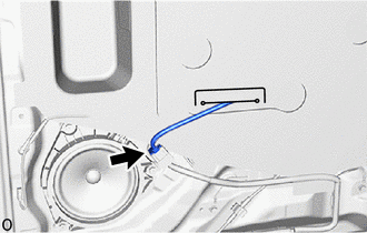
Connect the connector.
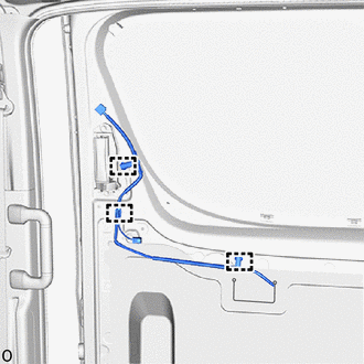
Attach the clamp as shown in the illustration.
62345B
40.INSTALL NO. 3 SLIDE DOOR WEATHERSTRIP RH
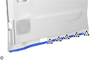
Attach the clip and install the No. 3 slide door weatherstrip RH.
67680B
41.INSTALL SLIDE DOOR TRIM BOARD ASSEMBLY RH

Connect the connector.
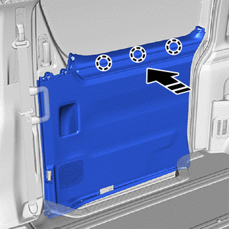
|
|
Install in this Direction |
Attach the claw in the direction indicated by the arrow shown in the illustration.
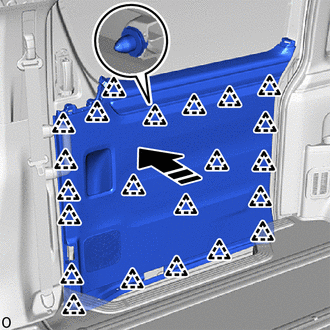
|
|
Install in this Direction |
Attach the clip and install the slide door trim board assembly RH in the direction indicated by the arrow shown in the illustration.
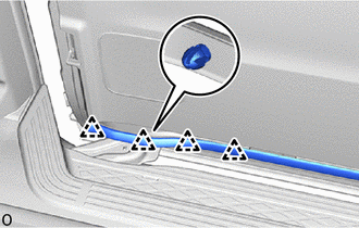
Attach the clip as shown in the illustration.
81380D
42.INSTALL STEP LIGHT ASSEMBLY
67487A
43.INSTALL REAR DOOR REAR GUIDE BRACKET GARNISH RH
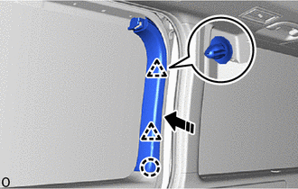
|
|
Install in this Direction |
Attach the claw and clip and install the rear door rear guide bracket garnish RH in the direction indicated by the arrow shown in the illustration.
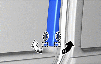

|
Place Hand Here |
|
|
Install in this Direction (1) |
|
|
Install in this Direction (2) |
Place your hand at the position shown in the illustration and attach the guide while pull in the installation direction.
67667A
44.INSTALL SLIDE DOOR WINDOW GARNISH RH
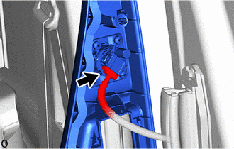
w/ Rear No. 2 Speaker assembly:
Connect the connector.
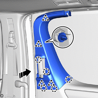
|
|
Install in this Direction |
Attach the claw and clip and install the slide door window garnish RH in the direction indicated by the arrow shown in the illustration.
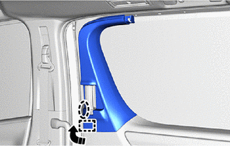
|
|
Place Hand Here |
|
|
Install in this Direction |
Place your hand at the position shown in the illustration and attach the guide while pull in the installation direction.
65988A
45.INSTALL SUNSHADE HOOK (w/ Sunshade)
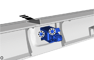
|
|
Install in this Direction |
Attach the claw and install the sunshade hook in the direction indicated by the arrow shown in the illustration.
- HINT:
-
Use the same procedure described for the other side.
67692B
46.INSTALL SLIDE DOOR TRIM UPPER COVER RH
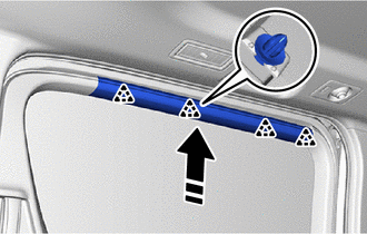
|
|
Install in this Direction |
Attach the clip and install the slide door trim upper cover RH in the direction indicated by the arrow shown in the illustration.
- HINT:
-
Install the sunshade hook together with the slide door trim upper cover RH.
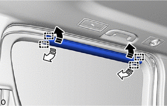
|
|
Install in this Direction (1) |
|
|
Install in this Direction (2) |
Attach the guide in the direction indicated by the arrow shown in the illustration.
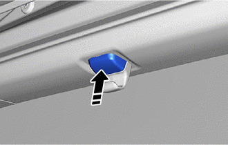
|
|
Install in this Direction |
w/ Sunshade
Attach the pin in the direction indicated by the arrow shown in the illustration.
- HINT:
-
Use the same procedure described for the other side.
47.CONNECT CABLE TO NEGATIVE BATTERY TERMINAL (w/ Rear Curtain Shield Airbag)
48. INITIALIZATION AFTER RECONNECTING BATTERY TERMINAL (w/ Rear Curtain Shield Airbag)
- HINT:
-
When disconnecting and reconnecting the battery, there is an automatic learning function that completes learning when the respective system is used.
49.INSPECT SRS WARNING LIGHT (w/ Rear Curtain Shield Airbag)
50. PERFORM DIAGNOSTIC SYSTEM CHECK (w/ Rear Curtain Shield Airbag)
51. CHECK POWER DOOR LOCK CONTROL SYSTEM
52. INITIALIZE POWER SLIDE DOOR SYSTEM