DOOR LOCK POWER DOOR LOCK CONTROL SYSTEM B1243 GSW Terminal Circuit Malfunction
DESCRIPTION
If the collision door lock release function does not operate normally, or an open or short in the GSW input circuit of the main body ECU (multiplex network body ECU) is detected, DTC B1243 will be stored.
| DTC No. | Detection Item | DTC Detection Condition | Trouble Area |
|---|---|---|---|
| B1243 | GSW Terminal Circuit Malfunction | A malfunction occurs in the GSW input circuit of the main body ECU (multiplex network body ECU). | ·
Main body ECU (multiplex network body ECU) ·
Instrument panel junction block assembly ·
Airbag ECU assembly ·
Harness or connector |
WIRING DIAGRAM
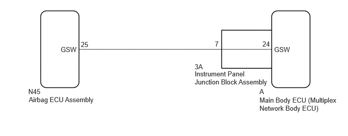
CAUTION / NOTICE / HINT
- NOTICE:
- ·
After turning the ignition switch off, waiting time may be required before disconnecting the cable from the negative (-) battery terminal. Therefore, make sure to read the disconnecting the cable from the negative (-) battery terminal notices before proceeding with work.
·If the main body ECU (multiplex network body ECU) is replaced, refer to the Service Bulletin.*
*: w/ Entry and Start System
·When DTC B1243 is output, the collision door lock release, shift-linked automatic door lock/unlock and speed-sensitive automatic door lock functions are prohibited.
·The vehicle is equipped with a Supplemental Restraint System (SRS) which includes components such as airbags. Before servicing (including removal or installation of parts), be sure to read the precaution for Supplemental Restraint System.
for Type A:
for Type C:
PROCEDURE
Clear the DTCs.
- Body Electrical > Main Body > Clear DTCs
- 50002 123
- Result:
Proceed to NEXT
NEXT
Recheck for DTCs.
- Body Electrical > Main Body > Trouble Codes
- 50001 123
- OK:
DTC B1243 is not output.
- Result:
Proceed to OK NG
OK
NG
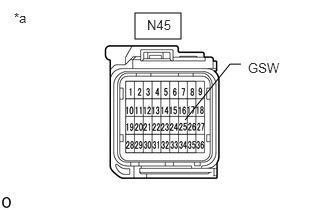
| *a | Front view of wire harness connector
(to Airbag ECU Assembly) |
Disconnect the cable from the negative (-) battery terminal.
- CAUTION:
-
Wait at least 90 seconds after disconnecting the cable from the negative (-) battery terminal to disable the SRS system.
- NOTICE:
-
Turning the ignition switch to ON with the airbag ECU assembly connector disconnected causes other DTCs to be stored. Clear the DTCs after performing this inspection.
Disconnect the airbag ECU assembly connector.
Connect the cable to the negative (-) battery terminal, and wait for at least 2 seconds.
Measure the voltage according to the value(s) in the table below.
- Standard Voltage:
Tester Connection Switch Condition Specified Condition N45-25 (GSW) - Body ground Ignition switch ON 4.3 to 5.5 V
- Result:
Proceed to OK NG
OK
NG
Disconnect the cable from the negative (-) battery terminal.
- CAUTION:
-
Wait at least 90 seconds after disconnecting the cable from the negative (-) battery terminal to disable the SRS system.
Disconnect the 3A instrument panel junction block assembly connector.
Disconnect the N45 airbag ECU assembly connector.
Measure the resistance according to the value(s) in the table below.
- Standard Resistance:
Tester Connection Condition Specified Condition 3A-7 - N45-25 (GSW) Always Below 1 Ω 3A-7 or N45-25 (GSW) - Other terminals and body ground Always 10 kΩ or higher
- Result:
Proceed to OK NG
OK
NG
Remove the instrument panel junction block assembly.
Remove the main body ECU (multiplex network body ECU) from the instrument panel junction block assembly.
Measure the resistance according to the value(s) in the table below.
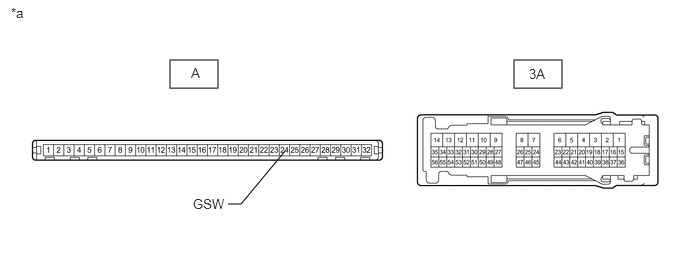
| *a | Component without harness connected
(Instrument Panel Junction Block Assembly) |
- | - |
- Standard Resistance:
Tester Connection Condition Specified Condition A-24 (GSW) - 3A-7 Always Below 1 Ω
- Result:
Proceed to OK NG
OK
NG