DOOR LOCK WIRELESS DOOR LOCK CONTROL SYSTEM(w/ Entry and Start System) TERMINALS OF ECU
CHECK INSTRUMENT PANEL JUNCTION BLOCK ASSEMBLY AND MAIN BODY ECU (MULTIPLEX NETWORK BODY ECU)
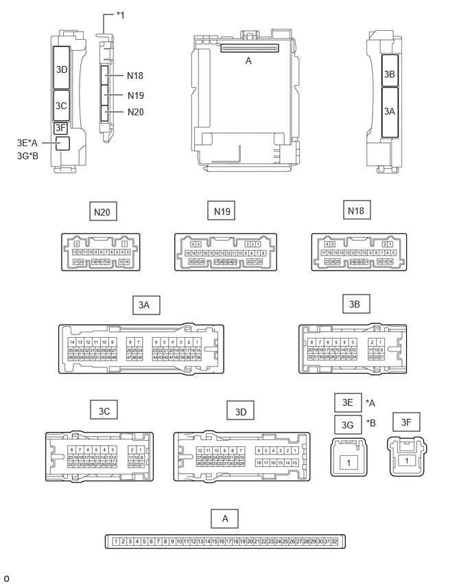
| *A | for LHD | *B | for RHD |
| *1 | Main Body ECU (Multiplex Network Body ECU) | - | - |
Remove the main body ECU (multiplex network body ECU) from the instrument panel junction block assembly.
Reconnect the instrument panel junction block assembly connectors.
Measure the voltage and resistance according to the value(s) in the table below.
| Tester Connection | Wiring Color | Input/Output | Terminal Description | Condition | Specified Condition | Related Data List Item |
|---|---|---|---|---|---|---|
| A-11 (GND1) - Body ground | - | - | Ground | Always | Below 1 Ω | - |
| A-30 (ACC) - Body ground | - | Input | ACC power supply | Engine switch on (ACC) | 11 to 14 V | ACC SW |
| Engine switch off | Below 1 V | |||||
| A-31 (BECU) - Body ground | - | Input | Battery power supply | Always | 11 to 14 V | - |
| A-32 (IG) - Body ground | - | Input | IG power supply | Engine switch on (IG) | 11 to 14 V*1
10.5 to 16 V*2 |
IG SW |
| Engine switch off | Below 1 V |
*1: w/o Stop and Start System
*2: w/ Stop and Start System
Install the main body ECU (multiplex network body ECU) to the instrument panel junction block assembly.
Measure the voltage and check for pulses according to the value(s) in the table below.
| Tester Connection | Wiring Color | Input/Output | Terminal Description | Condition | Specified Condition | Related Data List Item |
|---|---|---|---|---|---|---|
| 3C-29 (BZR) - Body ground | W - Body ground | Output | Wireless door lock buzzer output | Active Test Wireless Buzzer on | Pulse generation
(frequency: 2 kHz, high voltage: 11 to 14 V, low voltage: below 1 V) |
- |
| Active Test Wireless Buzzer off | Below 1 V |
CHECK CERTIFICATION ECU (SMART KEY ECU ASSEMBLY)
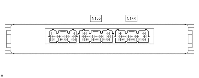
Disconnect the N156 certification ECU (smart key ECU assembly) connector.
Measure the voltage and resistance according to the value(s) in the table below.
| Tester Connection | Wiring Color | Input/Output | Terminal Description | Condition | Specified Condition | Related Data List Item |
|---|---|---|---|---|---|---|
| N156-18 (E) - Body ground | BR - Body ground | - | Ground | Always | Below 1 Ω | - |
| N156-4 (+B) - Body ground | Y - Body ground | Input | Power supply | Always | 11 to 14 V | - |
Reconnect the N156 certification ECU (smart key ECU assembly) connector.
Measure the voltage and check for pulses according to the value(s) in the table below.
| Tester Connection | Wiring Color | Input/Output | Terminal Description | Condition | Specified Condition | Related Data List Item |
|---|---|---|---|---|---|---|
| N155-18 (RCO) - N156-18 (E) | G - BR | Output | Output to door control receiver
(Power supply for door control receiver. Certification ECU (smart key ECU assembly) outputs 5 V when receiver starts operating.) |
Procedure:
1.
Engine switch off 2.
Electrical key transmitter sub-assembly brought outside detection area but kept inside wireless function operational area 3.
Lock or unlock switch of electrical key transmitter sub-assembly not pressed → pressed |
Pulse generation
(See waveform 1) |
- |
| N155-19 (RDAM) - N156-18 (E) | P - BR | Input | Door control receiver verifies data received from electrical key transmitter sub-assembly.
Door control receiver sends data from electrical key transmitter sub-assembly to certification ECU (smart key ECU assembly) (Door control receiver intermittently grounds 12 V signal from certification ECU (smart key ECU assembly)). |
Proceed:
1.
Engine switch off 2.
All doors locked 3.
Electrical key transmitter sub-assembly not inside vehicle 4.
Electrical key transmitter sub-assembly brought outside detection area but kept inside wireless function operational area 5.
Lock or unlock switch of electrical key transmitter sub-assembly not pressed → pressed |
Pulse generation
(See waveform 2) |
- |
| N155-20 (CSEL) - N156-18 (E) | GR - BR | Output | Communication channel switching circuit | Procedure:
1.
Engine switch off 2.
All doors closed |
Below 1 V → pulse generation | - |
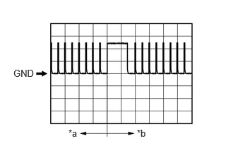
| *a | Before lock or unlock switch of electrical key transmitter sub-assembly pressed |
| *b | After lock or unlock switch of electrical key transmitter sub-assembly pressed |
Using an oscilloscope, check waveform 1.
- HINT:
-
The oscilloscope waveform shown in the illustration is an example for reference only. Noise, chattering, etc. are not shown.
| Item | Content |
|---|---|
| Tester Connection | N155-18 (RCO) - N156-18 (E) |
| Tool Setting | 2 V/DIV., 500 ms/DIV. |
| Condition | Procedure:
1.
Engine switch off 2.
Electrical key transmitter sub-assembly brought outside detection area but kept inside wireless function operational area 3.
Lock or unlock switch of electrical key transmitter sub-assembly not pressed → pressed |
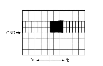
| *a | Before lock or unlock switch of electrical key transmitter sub-assembly pressed |
| *b | After lock or unlock switch of electrical key transmitter sub-assembly pressed |
Using an oscilloscope, check waveform 2.
- HINT:
-
The oscilloscope waveform shown in the illustration is an example for reference only. Noise, chattering, etc. are not shown.
| Item | Content |
|---|---|
| Tester Connection | N155-19 (RDAM) - N156-18 (E) |
| Tool Setting | 5 V/DIV., 500 ms/DIV. |
| Condition | Procedure:
1.
Engine switch off 2.
All doors locked 3.
Electrical key transmitter sub-assembly not inside vehicle 4.
Electrical key transmitter sub-assembly brought outside detection area but kept inside wireless function operational area 5.
Lock or unlock switch of electrical key transmitter sub-assembly not pressed → pressed |