NAVIGATION / MULTI INFO DISPLAY NAVIGATION SYSTEM Vehicle Speed Signal Circuit between Stereo Component Amplifier and Combination Meter
DESCRIPTION
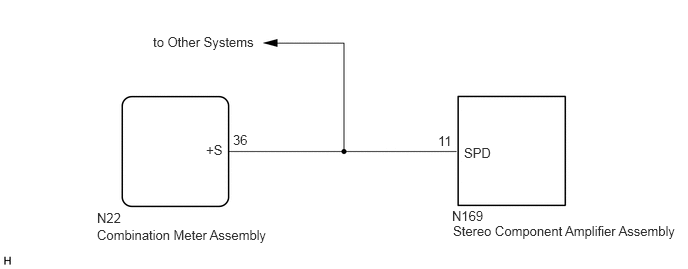
The stereo component amplifier assembly receives a vehicle speed signal from the combination meter assembly to control the ASL function.
- HINT:
- ·
A voltage of 12 V or 5 V is output from each ECU and then input to the combination meter assembly. The signal is changed to a pulse signal at the transistor in the combination meter assembly. Each ECU controls its respective systems based on this pulse signal.
·If a short occurs in any of the ECUs or in the wire harness connected to an ECU, all systems in the following diagram will not operate normally.
WIRING DIAGRAM
PROCEDURE
| *a | Component with harness connected
(Combination Meter Assembly) |
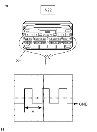
Check the output waveform.
Remove the combination meter assembly with the connector(s) still connected.
Connect an oscilloscope to terminal N22-36 (+S) and body ground.
Turn the ignition switch to ON.
Turn a wheel slowly.
Check the signal waveform according to the condition(s) in the table below.
| Item | Condition |
|---|---|
| Measurement terminal | N22-36 (+S) - Body ground |
| Tool setting | 5 V/DIV., 20 ms./DIV. |
| Vehicle condition | Wheel being rotated |
- OK:
The waveform is similar to that shown in the illustration.
- HINT:
-
When the system is functioning normally, one wheel revolution generates 4 pulses. As the vehicle speed increases, the width indicated by (A) in the illustration narrows.
- Result:
Proceed to OK NG
OK
NG
Check the input waveform.

| *a | Component with harness connected
(Stereo Component Amplifier Assembly) |
- | - |
Remove the stereo component amplifier assembly with the connector(s) still connected.
Connect an oscilloscope to terminal N169-11 (SPD) and body ground.
Turn the ignition switch to ON.
Turn a wheel slowly.
Check the signal waveform according to the condition(s) in the table below.
| Item | Condition |
|---|---|
| Measurement terminal | N169-11 (SPD) - Body ground |
| Tool setting | 5 V/DIV., 20 ms./DIV. |
| Vehicle condition | Wheel being rotated |
- OK:
The waveform is similar to that shown in the illustration.
- HINT:
-
When the system is functioning normally, one wheel revolution generates 4 pulses. As the vehicle speed increases, the width indicated by (A) in the illustration narrows.
- Result:
Proceed to OK NG
OK
NG