LIGHTING (INT) LIGHTING SYSTEM TERMINALS OF ECU
CHECK INSTRUMENT PANEL JUNCTION BLOCK ASSEMBLY AND MAIN BODY ECU (MULTIPLEX NETWORK BODY ECU)
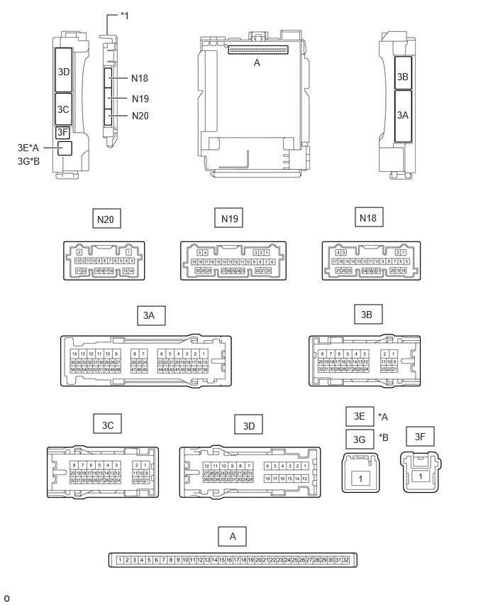
| *A | for LHD | *B | for RHD |
| *1 | Main Body ECU (Multiplex Network Body ECU) | - | - |
Remove the main body ECU (multiplex network body ECU) from the instrument panel junction block assembly.
Connect the instrument panel junction block assembly connectors.
Measure the voltage and resistance according to the value(s) in the table below.
| Terminal No. (Symbol) | Wiring Color | Terminal Description | Condition | Specified Condition |
|---|---|---|---|---|
|
*1: w/o Stop and Start System *2: w/ Stop and Start System |
||||
| A-32 (IG) - Body ground | None - Body ground | Ignition power supply | Ignition switch ON | 11 to 14 V*1
10.5 to 16 V*2 |
| Ignition switch off | Below 1 V | |||
| A-31 (BECU) - Body ground | None - Body ground | Battery power supply | Always | 11 to 14 V |
| A-30 (ACC) - Body ground | None - Body ground | ACC power supply | Ignition switch ACC | 11 to 14 V |
| Ignition switch off | Below 1 V | |||
| A-11 (GND1) - Body ground | None - Body ground | Ground | Always | Below 1 Ω |
Install the main body ECU (multiplex network body ECU).
Measure the voltage and pulse according to the value(s) in the table below.
| Terminal No. (Symbol) | Wiring Color | Terminal Description | Condition | Specified Condition |
|---|---|---|---|---|
|
*1: w/ Ignition Linked Automatic Door Unlock Function *2: w/ Step light, w/o Ignition Linked Automatic Door Unlock Function *3: w/ Immobiliser System, w/o Ignition Linked Automatic Door Unlock Function *4: w/ Slide Door LH *5: w/ Slide Door RH *6: for Wagon *7: w/ Color Change Function *8: w/o Color Change Function |
||||
| N19-1 (FLCY) - Body ground | R - Body ground | Front door courtesy light switch assembly LH input | Front door LH open | Below 1 V |
| Front door LH closed | 4.7 to 5.3 V | |||
| N19-6 (FRCY) - Body ground | R - Body ground | Front door courtesy light switch assembly RH input | Front door RH open | Below 1 V |
| Front door RH closed | 4.7 to 5.3 V | |||
| 3D-24 (LCTY) - Body ground*4 | LA-R - Body ground | Rear door courtesy light switch assembly LH input | Slide door LH open | Below 1 V |
| Slide door LH closed | 4.7 to 5.3 V | |||
| 3A-31 (RCTY) - Body ground*5 | LA-G - Body ground | Rear door courtesy light switch assembly RH input | Slide door RH open | Below 1 V |
| Slide door RH closed | 4.7 to 5.3 V | |||
| 3D-34 (BCTY) - Body ground | L - Body ground | Back door courtesy light switch input | Back door open | Below 1 V |
| Back door closed | 4.7 to 5.3 V | |||
| 3B-13 (LSFL) - Body ground | B - Body ground | Front door LH unlock detection switch input | Front door LH locked | Pulse generation |
| Front door LH unlocked | Below 1 V | |||
| 3B-12 (LSFR) - Body ground | B - Body ground | Front door RH unlock detection switch input | Front door RH locked | Pulse generation |
| Front door RH unlocked | Below 1 V | |||
| 3B-14 (LSWL) - Body ground*4 | L - Body ground | Slide door LH unlock detection switch input | Slide door LH locked | Pulse generation |
| Slide door LH unlocked | Below 1 V | |||
| N18-20 (LSWR) - Body ground*5 | L - Body ground | Slide door RH unlock detection switch input | Slide door RH locked | Pulse generation |
| Slide door RH unlocked | Below 1 V | |||
| N19-18 (ILEW) - Body ground*1 | B - Body ground | Room light switch input | Room light switch off | 11 to 14 V |
| Room light switch on | Below 1 V | |||
| N19-27 (LSWB) - Body ground | GR - Body ground | Back door unlock detection switch input | Back door locked | Pulse generation |
| Back door unlocked | Below 1 V | |||
| N18-5 (LCYL) - Body ground*2 | P - Body ground | Step light LH input | Step light LH on | Below 1 V |
| Step light LH off | 11 to 14 V | |||
| N18-18 (RCYL) - Body ground*2 | SB - Body ground | Step light RH input | Step light RH on | Below 1 V |
| Step light RH off | 11 to 14 V | |||
| 3B-9 - Body ground | B - Body ground | Interior lights drive output | DOME CUT relay off | 11 to 14 V |
| DOME CUT relay on | Below 1 V | |||
| 3D-19 - Body ground*3 | LA-B - Body ground | Interior lights drive output | DOME CUT relay off | 11 to 14 V |
| DOME CUT relay on | Below 1 V | |||
| 3A-53 - Body ground | LA-G - Body ground | Taillight signal | Ignition switch ON, light control switch TAIL | 11 to 14 V |
| Ignition switch ON, light control switch off | Below 1 V | |||
| 3D-22 - Body ground | LA-G - Body ground | Taillight signal | Ignition switch ON, light control switch TAIL | 11 to 14 V |
| Ignition switch ON, light control switch off | Below 1 V | |||
| N18-25 (FTSW) - Body ground*6 | GR - Body ground | Room light switch input | Room light switch off | 11 to 14 V |
| Room light switch on | Below 1 V | |||
| N18-7 (FCSW) - Body ground*7 | L - Body ground | No. 2 room light switch input | No. 2 room light switch off | 11 to 14 V |
| No. 2 room light switch on | Below 1 V | |||
| N19-14 (RTSW) - Body ground*6 | R - Body ground | Integration control and panel assembly (room light switch) input | Integration control and panel assembly (room light switch) off | 11 to 14 V |
| Integration control and panel assembly (room light switch) on | Below 1 V | |||
| N18-8 (RCSW) - Body ground*7 | L - Body ground | Integration control and panel assembly (No. 2 room light switch) input | Integration control and panel assembly (No. 2 room light switch) off | 11 to 14 V |
| Integration control and panel assembly (No. 2 room light switch) on | Below 1 V | |||
| N18-9 (RSW1) - Body ground*6 | BR - Body ground | Spot light assembly (spot light switch) (for Front RH) input | Spot light assembly (spot light switch) (for Front RH) off | 11 to 14 V |
| Spot light assembly (spot light switch) (for Front RH) on | Below 1 V | |||
| N19-15 (RSW2) - Body ground*6 | V - Body ground | Spot light assembly (spot light switch) (for Front LH) input | Spot light assembly (spot light switch) (for Front LH) off | 11 to 14 V |
| Spot light assembly (spot light switch) (for Front LH) on | Below 1 V | |||
| N18-10 (RSW3) - Body ground*6 | BR - Body ground | Spot light assembly (spot light switch) (for Rear RH) input | Spot light assembly (spot light switch) (for Rear RH) off | 11 to 14 V |
| Spot light assembly (spot light switch) (for Rear RH) on | Below 1 V | |||
| N19-17 (RSW4) - Body ground*6 | P - Body ground | Spot light assembly (spot light switch) (for Rear LH) input | Spot light assembly (spot light switch) (for Rear LH) off | 11 to 14 V |
| Spot light assembly (spot light switch) (for Rear LH) on | Below 1 V | |||
| N20-20 (LED1) - Body ground*6*8 | P - Body ground | Interior illumination light (slide door illumination, quarter trim illumination) input | Interior illumination light (slide door illumination, quarter trim illumination) off | 11 to 14 V |
| Interior illumination light (slide door illumination, quarter trim illumination) on | Below 1 V | |||
ROOM LIGHT CONTROL RELAY (for Front) (for Wagon)
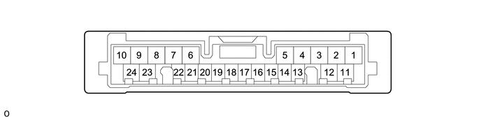
Disconnect the N148 room light control relay (for Front) connector.
Measure the voltage and resistance according to the value(s) in the table below.
| Terminal No. (Symbol) | Wiring Color | Terminal Description | Condition | Specified Condition |
|---|---|---|---|---|
| N148-7 (B) - Body ground | B - Body ground | Battery power supply | Always | 11 to 14 V |
| N148-9 (E) - Body ground | W-B - Body ground | Ground | Always | Below 1 Ω |
Reconnect the N148 room light control relay (for Front) connector.
Measure the voltage and waveform according to the value(s) in the table below.
| Terminal No. (Symbol) | Wiring Color | Terminal Description | Condition | Specified Condition |
|---|---|---|---|---|
| N148-11 (ILA1) - Body ground | GR - Body ground | Spot light assembly (for Front RH) signal | Spot light assembly (for Front RH) illuminated | Below 1 V |
| Spot light assembly (for Front RH) not illuminated | 11 to 14 V | |||
| Spot light assembly (for Front RH) not illuminated → spot light assembly (spot light switch) (for Front RH) operated 2 or 3 times | Pulse generation | |||
| N148-12 (ILA2) - Body ground | R - Body ground | Spot light assembly (for Rear RH) signal | Spot light assembly (for Rear RH) illuminated | Below 1 V |
| Spot light assembly (for Rear RH) not illuminated | 11 to 14 V | |||
| Spot light assembly (for Rear RH) not illuminated → spot light assembly (spot light switch) (for Rear RH) operated 2 or 3 times | Pulse generation | |||
| N148-13 (ILA3) - Body ground | L - Body ground | Spot light assembly (for Front LH) signal | Spot light assembly (for Front LH) illuminated | Below 1 V |
| Spot light assembly (for Front LH) not illuminated | 11 to 14 V | |||
| Spot light assembly (for Front LH) not illuminated → spot light assembly (spot light switch) (for Front LH) operated 2 or 3 times | Pulse generation | |||
| N148-14 (ILA4) - Body ground | SB - Body ground | Spot light assembly (for Rear LH) signal | Spot light assembly (for Rear LH) illuminated | Below 1 V |
| Spot light assembly (for Rear LH) not illuminated | 11 to 14 V | |||
| Spot light assembly (for Rear LH) not illuminated → spot light assembly (spot light switch) (for Rear LH) operated 2 or 3 times | Pulse generation |
ROOM LIGHT CONTROL RELAY (for Rear) (w/ Color Change Function)
Disconnect the V33 room light control relay (for Rear) connector.
Measure the voltage and resistance according to the value(s) in the table below.
| Terminal No. (Symbol) | Wiring Color | Terminal Description | Condition | Specified Condition |
|---|---|---|---|---|
| V33-7 (BU+) - Body ground | R - Body ground | Battery power supply | Always | 11 to 14 V |
| V33-9 (BU-) - Body ground | W-B - Body ground | Ground | Always | Below 1 Ω |
Reconnect the V33 room light control relay (for Rear) connector.
Measure the voltage and waveform according to the value(s) in the table below.
| Terminal No. (Symbol) | Wiring Color | Terminal Description | Condition | Specified Condition |
|---|---|---|---|---|
| V33-11 (ILB1) - Body ground | R - Body ground | Slide door illumination and quarter trim illumination signal | The following lights illuminated (blue):
·
No. 1 interior illumination light assembly (Slide Door Illumination) ·
No. 2 interior illumination light assembly (Slide Door Illumination) ·
No. 1 interior illumination light assembly (Quarter Trim Illumination) ·
No. 2 interior illumination light assembly (Quarter Trim Illumination) |
Below 1 V |
| The following lights not illuminated (blue):
·
No. 1 interior illumination light assembly (Slide Door Illumination) ·
No. 2 interior illumination light assembly (Slide Door Illumination) ·
No. 1 interior illumination light assembly (Quarter Trim Illumination) ·
No. 2 interior illumination light assembly (Quarter Trim Illumination) |
11 to 14 V | |||
| V33-12 (ILB2) - Body ground | G - Body ground | Slide door illumination and quarter trim illumination signal | The following lights illuminated (white):
·
No. 1 interior illumination light assembly (Slide Door Illumination) ·
No. 2 interior illumination light assembly (Slide Door Illumination) ·
No. 1 interior illumination light assembly (Quarter Trim Illumination) ·
No. 2 interior illumination light assembly (Quarter Trim Illumination) |
Below 1 V |
| The following lights not illuminated (white):
·
No. 1 interior illumination light assembly (Slide Door Illumination) ·
No. 2 interior illumination light assembly (Slide Door Illumination) ·
No. 1 interior illumination light assembly (Quarter Trim Illumination) ·
No. 2 interior illumination light assembly (Quarter Trim Illumination) |
11 to 14 V | |||
| V33-13 (ILB3) - Body ground | GR - Body ground | Slide door illumination and quarter trim illumination signal | The following lights illuminated (amber):
·
No. 1 interior illumination light assembly (Slide Door Illumination) ·
No. 2 interior illumination light assembly (Slide Door Illumination) ·
No. 1 interior illumination light assembly (Quarter Trim Illumination) ·
No. 2 interior illumination light assembly (Quarter Trim Illumination) |
Below 1 V |
| The following lights not illuminated (amber):
·
No. 1 interior illumination light assembly (Slide Door Illumination) ·
No. 2 interior illumination light assembly (Slide Door Illumination) ·
No. 1 interior illumination light assembly (Quarter Trim Illumination) ·
No. 2 interior illumination light assembly (Quarter Trim Illumination) |
11 to 14 V |
CERTIFICATION ECU (SMART KEY ECU ASSEMBLY) (w/ Entry and Start System)
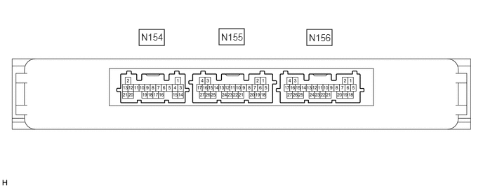
Disconnect the N156 certification ECU (smart key ECU assembly) connector.
Measure the voltage and resistance according to the value(s) in the table below.
| Terminal No. (Symbol) | Wiring Color | Terminal Description | Condition | Specified Condition |
|---|---|---|---|---|
| N156-18 (E) - Body ground | BR - Body ground | Battery power supply | Always | 11 to 14 V |
| N156-18 (E) - Body ground | Y - BR | Battery power supply | Always | 11 to 14 V |
| N156-15 (CUTB) - N156-18 (E) | BE - BR | Ground | Always | Below 1 Ω |
Reconnect the N156 certification ECU (smart key ECU assembly) connector.
Measure the voltage according to the value(s) in the table below.
| Terminal No. (Symbol) | Wiring Color | Terminal Description | Condition | Specified Condition |
|---|---|---|---|---|
| N156-10 (SWIL) - N156-11 (AGND) | P - LG | Push start switch illumination drive output | Push start switch illumination on | 11 to 14 V |
| Push start switch illumination off | Below 1 V |