HEATING / AIR CONDITIONING AIR CONDITIONING SYSTEM(for Heater System) Recirculated/Fresh Air Modes do not Switch
DESCRIPTION
If the fresh/recirculation mode does not change or exhaust gas can be smelled even while set to recirculation mode, the following causes are possible.
| Malfunction Status | Factor |
|---|---|
·
Fresh/recirculation mode does not change. ·
Exhaust gas can be smelled even while set to recirculation mode. |
·
Blower servo motor malfunction ·
Blower damper and link operation (jamming) ·
Foreign object jammed in door ·
Air conditioning radiator assembly malfunction |
WIRING DIAGRAM
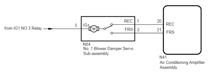
PROCEDURE
Check that the No. 1 blower damper servo sub-assembly is installed correctly.
- OK:
No. 1 blower damper servo sub-assembly is installed correctly.
- Result:
Proceed to OK NG
OK
NG
Remove the No. 1 blower damper servo sub-assembly.
Inspect the No. 1 blower damper servo sub-assembly.
- Result:
Proceed to OK NG
OK
NG
Disconnect the N84 No. 1 blower damper servo motor sub-assembly connector.
Disconnect the N41 air conditioning amplifier assembly connector.
Measure the voltage according to the value(s) in the table below.
- Standard Voltage:
Tester Connection Switch Condition Specified Condition N84-5 (IG+) - Body ground Ignition switch ON 11 to 14 V N84-5 (IG+) - Body ground Ignition switch off Below 1 V
Measure the resistance according to the value(s) in the table below.
- Standard Resistance:
Tester Connection Condition Specified Condition N84-1 (REC) - N41-20 (REC) Always Below 1 Ω N84-2 (FRS) - N41-21 (FRS) Always Below 1 Ω N84-1 (REC) or N41-20 (REC) - Body ground Always 10 kΩ or higher N84-2 (FRS) or N41-21 (FRS) - Body ground Always 10 kΩ or higher
- Result:
Proceed to OK NG
OK
NG