HEATING / AIR CONDITIONING BLOWER UNIT REASSEMBLY
PROCEDURE

 87130K
1.INSTALL NO. 1 BLOWER DAMPER SERVO SUB-ASSEMBLY (for LHD)
87130K
1.INSTALL NO. 1 BLOWER DAMPER SERVO SUB-ASSEMBLY (for LHD)
for Automatic Air Conditioning System:
Connect the 2 links of the blower assembly to the 2 holes on the plate of the No. 1 blower damper servo sub-assembly as shown in the illustration.
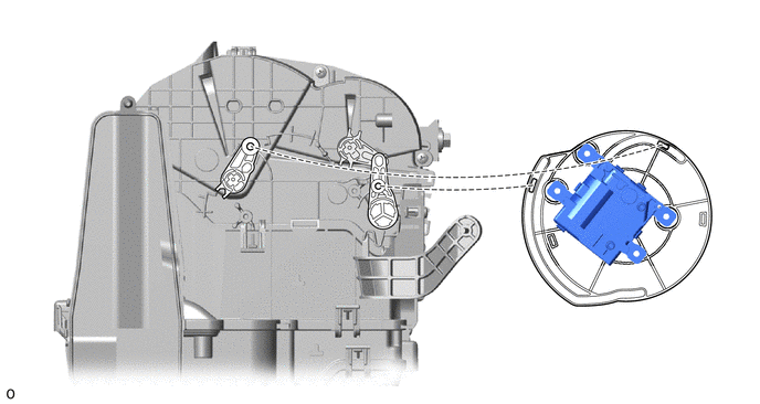
| *a | Link | *b | Hole |
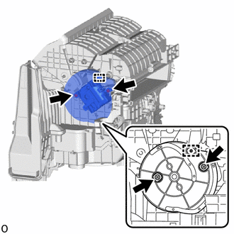
Attach the guide.
Install the No. 1 blower damper servo sub-assembly with the 2 screws.
except Automatic Air Conditioning System:
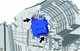
Attach the guide.
Install the No. 1 blower damper servo sub-assembly with the 2 screws.
87130K
2.INSTALL NO. 1 BLOWER DAMPER SERVO SUB-ASSEMBLY (for RHD)
for Automatic Air Conditioning System:
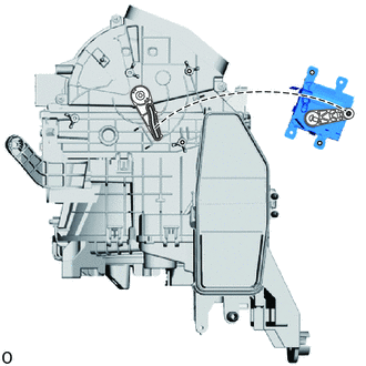
| *a | Link |
| *b | Hole |
Connect the link of the blower assembly to the hole on the plate of the No. 1 blower damper servo sub-assembly as shown in the illustration.
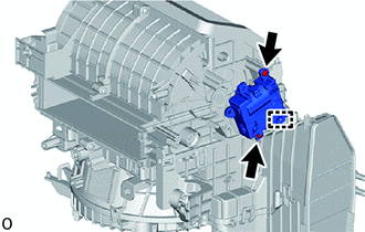
Attach the guide.
Install the No. 1 blower damper servo sub-assembly with the 2 screws.
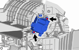
except Automatic Air Conditioning System:
Attach the guide.
Install the No. 1 blower damper servo sub-assembly with the 2 screws.
3.INSTALL BLOWER RESISTOR (except Automatic Air Conditioning System)
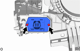
for LHD:
Install the blower resistor with the 2 screws.
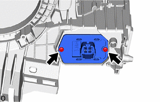
for RHD:
Install the blower resistor with the 2 screws.
87103B
4.INSTALL BLOWER WITH FAN MOTOR SUB-ASSEMBLY
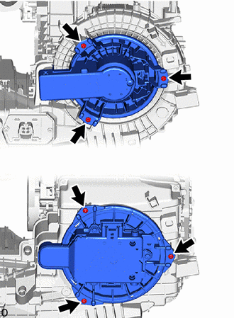
| *A | except Automatic Air Conditioning System |
| *B | for Automatic Air Conditioning System |
for LHD:
Install the blower with fan motor sub-assembly with the 3 screws.
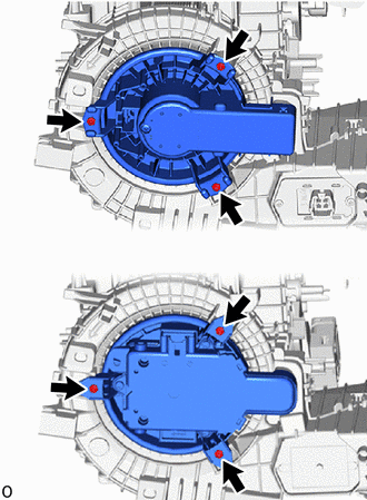
| *A | except Automatic Air Conditioning System |
| *B | for Automatic Air Conditioning System |
for RHD:
Install the blower with fan motor sub-assembly with the 3 screws.
87139C
5.INSTALL CLEAN AIR FILTER
for LHD, Two Layer Blower Type:
Attach the guide on the cutout side of the air filter case and then attach the guide as shown in the illustration to install the clean air filter.
- NOTICE:
- ·
Do not apply excessive force to the filter medium, as doing so may damage it.
·Make sure that the "UP" marks are facing the correct direction before installing the clean air filter.
·Make sure that there is no clearance between the clean air filter and air filter case and that the clean air filter is not deformed.
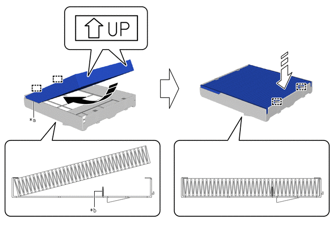
| *a | Cutout | *b | Rib |

|
Install in this Direction (1) | 
|
Install in this Direction (2) |
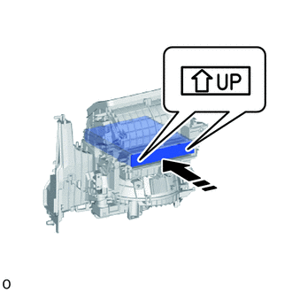
|
|
Install in this Direction |
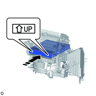
for LHD, Single Layer Blower Type:
Align the "UP" marks as shown in the illustration and install the clean air filter.
- NOTICE:
-
Insert so that the UP mark arrow is pointing upwards.
|
|
Install in this Direction |
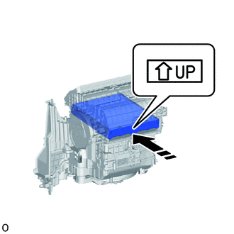
for RHD:
Align the "UP" marks as shown in the illustration and install the clean air filter.
- NOTICE:
-
Insert so that the UP mark arrow is pointing upwards.
88548B
6.INSTALL AIR FILTER CASE
|
|
Install in this Direction |
for LHD, Two Layer Blower Type:
Align the "UP" marks as shown in the illustration and install the air filter case.
- NOTICE:
-
Insert so that the UP mark arrow is pointing upwards.
88899M
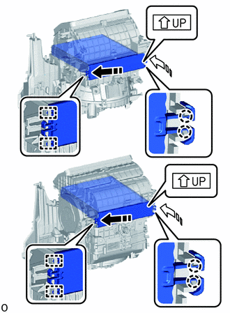
7.INSTALL AIR FILTER COVER PLATE
| *A | Single Layer Blower Type |
| *B | Two Layer Blower Type |
|
|
Install in this Direction (1) |
|
|
Install in this Direction (2) |
for LHD:
Insert the guide in the direction indicated by the arrow shown in the illustration.
Rotate in the direction indicated by the arrow shown in the illustration, attach the claw and install the air filter cover plate in the order shown in the illustration.
- NOTICE:
- ·
Insert it with the arrow of the UP mark facing upward.
·Insert the claw until a "click" sound is heard.
|
|
Install in this Direction (1) |
|
|
Install in this Direction (2) |
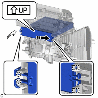
for RHD:
Insert the guide in the direction indicated by the arrow shown in the illustration.
Rotate in the direction indicated by the arrow shown in the illustration, attach the claw and install the air filter cover plate in the order shown in the illustration.
- NOTICE:
- ·
Insert it with the arrow of the UP mark facing upward.
·Insert the claw until a "click" sound is heard.