NETWORKING LIN COMMUNICATION SYSTEM B1206 P/W Master Switch Communication Stop B2321 D-Door Motor ECU Communication Stop B2322 P-Door Motor ECU Communication Stop
DESCRIPTION
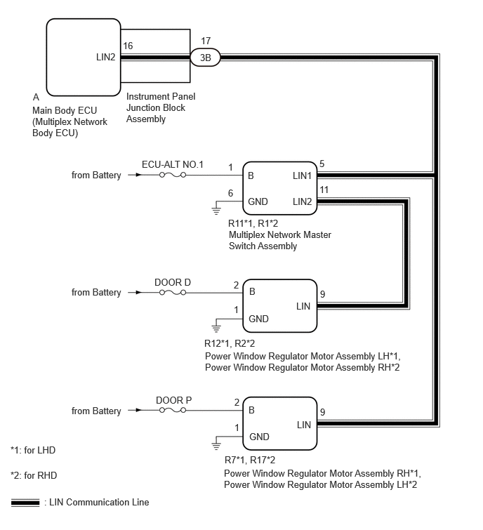
This DTC is stored when LIN communication between the main body ECU (multiplex network body ECU) and multiplex network master switch assembly, power window regulator motor assembly LH and power window regulator motor assembly RH stops for 10 seconds or more.
| DTC No. | Detection Item | DTC Detection Condition | Trouble Area |
|---|---|---|---|
| B1206 | P/W Master Switch Communication Stop | No communication between multiplex network master switch assembly and main body ECU (multiplex network body ECU) for 10 seconds or more. | ·
Main body ECU (multiplex network body ECU) ·
Instrument panel junction block assembly ·
Multiplex network master switch assembly ·
Harness or connector |
| B2321 | D-Door Motor ECU Communication Stop | ·
No communication between power window regulator motor assembly LH and main body ECU (multiplex network body ECU) for 10 seconds or more. (for LHD) ·
No communication between power window regulator motor assembly RH and main body ECU (multiplex network body ECU) for 10 seconds or more. (for RHD) |
·
Main body ECU (multiplex network body ECU) ·
Instrument panel junction block assembly ·
Multiplex network master switch assembly ·
Power window regulator motor assembly LH (for LHD) ·
Power window regulator motor assembly RH (for RHD) ·
Harness or connector |
| B2322 | P-Door Motor ECU Communication Stop | ·
No communication between power window regulator motor assembly RH and main body ECU (multiplex network body ECU) for 10 seconds or more. (for LHD) ·
No communication between power window regulator motor assembly LH and main body ECU (multiplex network body ECU) for 10 seconds or more. (for RHD) |
·
Main body ECU (multiplex network body ECU) ·
Instrument panel junction block assembly ·
Power window regulator motor assembly RH (for LHD) ·
Power window regulator motor assembly LH (for RHD) ·
Harness or connector |
WIRING DIAGRAM
CAUTION / NOTICE / HINT
- NOTICE:
- ·
Inspect the fuses for circuits related to this system before performing the following procedure.
·When a power window regulator motor assembly is replaced or removed and reinstalled, it is necessary to perform initialization.
PROCEDURE
Clear the DTCs.
- Body Electrical > Main Body > Clear DTCs
- 50002 123
Check for DTCs.
- Body Electrical > Main Body > Trouble Codes
- 50001 123
- Result:
Result Proceed to DTC is not output A DTC B1206, B2321 or B2322 are output B DTC B1206 and B2321 are output C Only DTC B1206 is output D Only DTC B2321 is output (for LHD) E Only DTC B2321 is output (for RHD) F Only DTC B2322 is output (for LHD) G Only DTC B2322 is output (for RHD) H
A
B
C
D
E
F
G
H
Disconnect the 3B instrument panel junction block assembly connector.
Disconnect the R11*1 or R1*2 multiplex network master switch assembly connector.
*1: for LHD
*2: for RHD
Measure the resistance according to the value(s) in the table below.
- Standard Resistance:
for LHD Tester Connection Condition Specified Condition 3B-17 - R11-5 (LIN1) Always Below 1 Ω
for RHD Tester Connection Condition Specified Condition 3B-17 - R1-5 (LIN1) Always Below 1 Ω
- Result:
Proceed to OK NG
OK
NG
Remove the instrument panel junction block assembly.
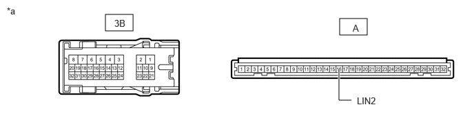
| *a | Component without harness connected
(Instrument Panel Junction Block Assembly) |
- | - |
Remove the main body ECU (multiplex network body ECU) from the instrument panel junction block assembly.
Measure the resistance according to the value(s) in the table below.
- Standard Resistance:
Tester Connection Condition Specified Condition 3B-17 - A-16 (LIN2) Always Below 1 Ω
- Result:
Proceed to OK NG
OK
NG
Disconnect the 3B instrument panel junction block assembly connector.
Disconnect the R11*1 or R1*2 multiplex network master switch assembly connector.
*1: for LHD
*2: for RHD
Measure the resistance according to the value(s) in the table below.
- Standard Resistance:
for LHD Tester Connection Condition Specified Condition 3B-17 - R11-5 (LIN1) Always Below 1 Ω
for RHD Tester Connection Condition Specified Condition 3B-17 - R1-5 (LIN1) Always Below 1 Ω
- Result:
Proceed to OK NG
OK
NG
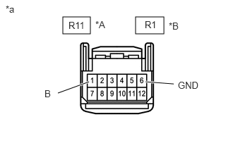
| *A | for LHD |
| *B | for RHD |
| *a | Front view of wire harness connector
(to Multiplex Network Master Switch Assembly) |
Disconnect the multiplex network master switch assembly connector.
Measure the voltage according to the value(s) in the table below.
- Standard Voltage:
for LHD Tester Connection Condition Specified Condition R11-1 (B) - Body ground Always 11 to 14 V
for RHD Tester Connection Condition Specified Condition R1-1 (B) - Body ground Always 11 to 14 V
Measure the resistance according to the value(s) in the table below.
- Standard Resistance:
for LHD Tester Connection Condition Specified Condition R11-6 (GND) - Body ground Always Below 1 Ω
for RHD Tester Connection Condition Specified Condition R1-6 (GND) - Body ground Always Below 1 Ω
- Result:
Proceed to OK NG
OK
NG
Disconnect the 3B instrument panel junction block assembly connector.
Disconnect the R12 power window regulator motor assembly LH connector.
Measure the resistance according to the value(s) in the table below.
- Standard Resistance:
Tester Connection Condition Specified Condition 3B-17 - R12-9 (LIN) Always Below 1 Ω
- Result:
Proceed to OK NG
OK
NG
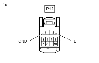
| *a | Front view of wire harness connector
(to Power Window Regulator Motor Assembly LH) |
Disconnect the power window regulator motor assembly LH connector.
Measure the voltage according to the value(s) in the table below.
- Standard Voltage:
Tester Connection Condition Specified Condition R12-2 (B) - Body ground Always 11 to 14 V
Measure the resistance according to the value(s) in the table below.
- Standard Resistance:
Tester Connection Condition Specified Condition R12-1 (GND) - Body ground Always Below 1 Ω
- Result:
Proceed to OK NG
OK
NG
Disconnect the R11 multiplex network master switch assembly connector.
Disconnect the R12 power window regulator motor assembly LH connector.
Measure the resistance according to the value(s) in the table below.
- Standard Resistance:
Tester Connection Condition Specified Condition R11-11 (LIN2) - R12-9 (LIN) Always Below 1 Ω
- Result:
Proceed to OK NG
OK
NG
Disconnect the 3B instrument panel junction block assembly connector.
Disconnect the R2 power window regulator motor assembly RH connector.
Measure the resistance according to the value(s) in the table below.
- Standard Resistance:
Tester Connection Condition Specified Condition 3B-17 - R2-9 (LIN) Always Below 1 Ω
- Result:
Proceed to OK NG
OK
NG
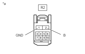
| *a | Front view of wire harness connector
(to Power Window Regulator Motor Assembly RH) |
Disconnect the power window regulator motor assembly RH connector.
Measure the voltage according to the value(s) in the table below.
- Standard Voltage:
Tester Connection Condition Specified Condition R2-2 (B) - Body ground Always 11 to 14 V
Measure the resistance according to the value(s) in the table below.
- Standard Resistance:
Tester Connection Condition Specified Condition R2-1 (GND) - Body ground Always Below 1 Ω
- Result:
Proceed to OK NG
OK
NG
Disconnect the R1 multiplex network master switch assembly connector.
Disconnect the R2 power window regulator motor assembly RH connector.
Measure the resistance according to the value(s) in the table below.
- Standard Resistance:
Tester Connection Condition Specified Condition R1-11 (LIN2) - R2-9 (LIN) Always Below 1 Ω
- Result:
Proceed to OK NG
OK
NG
Disconnect the 3B instrument panel junction block assembly connector.
Disconnect the R7 power window regulator motor assembly RH connector.
Measure the resistance according to the value(s) in the table below.
- Standard Resistance:
Tester Connection Condition Specified Condition 3B-17 - R7-9 (LIN) Always Below 1 Ω
- Result:
Proceed to OK NG
OK
NG
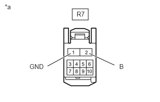
| *a | Front view of wire harness connector
(to Power Window Regulator Motor Assembly RH) |
Disconnect the power window regulator motor assembly RH connector.
Measure the voltage according to the value(s) in the table below.
- Standard Voltage:
Tester Connection Condition Specified Condition R7-2 (B) - Body ground Always 11 to 14 V
Measure the resistance according to the value(s) in the table below.
- Standard Resistance:
Tester Connection Condition Specified Condition R7-1 (GND) - Body ground Always Below 1 Ω
- Result:
Proceed to OK NG
OK
NG
Disconnect the 3B instrument panel junction block assembly connector.
Disconnect the R17 power window regulator motor assembly LH connector.
Measure the resistance according to the value(s) in the table below.
- Standard Resistance:
Tester Connection Condition Specified Condition 3B-17 - R17-9 (LIN) Always Below 1 Ω
- Result:
Proceed to OK NG
OK
NG
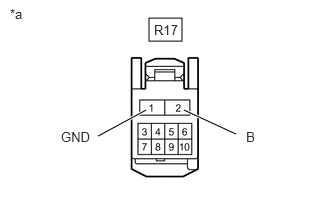
| *a | Front view of wire harness connector
(to Power Window Regulator Motor Assembly LH) |
Disconnect the power window regulator motor assembly LH connector.
Measure the voltage according to the value(s) in the table below.
- Standard Voltage:
Tester Connection Condition Specified Condition R17-2 (B) - Body ground Always 11 to 14 V
Measure the resistance according to the value(s) in the table below.
- Standard Resistance:
Tester Connection Condition Specified Condition R17-1 (GND) - Body ground Always Below 1 Ω
- Result:
Proceed to OK NG
OK
NG