WIPER / WASHER FRONT WIPER MOTOR INSTALLATION
CAUTION / NOTICE / HINT
- HINT:
- ·
Use the same procedure for RHD and LHD vehicles.
·The procedure listed below is for LHD vehicles.
PROCEDURE

 85110
1.INSTALL WINDSHIELD WIPER MOTOR ASSEMBLY
85110
1.INSTALL WINDSHIELD WIPER MOTOR ASSEMBLY
- NOTICE:
-
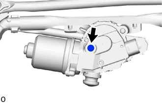
- ·
Do not touch the filter of waterproof cap.
·When installing the windshield wiper motor assembly, check the waterproof cap filter for any cracks or damage and that there is no grease on it.
·Do not reuse the windshield wiper motor assembly if it has been dropped or subjected to any strong impacts.
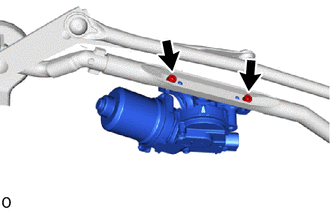
Using a T30 "TORX" socket wrench, install the windshield wiper motor assembly with the 2 "TORX" bolts.
- Torque:
- 7.5 N*m (76 kgf*cm, 66 in.*lbf)
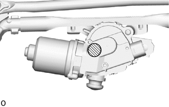

|
MP grease |
Apply MP grease to the windshield wiper motor crank pivot.
Install the No. 1 windshield wiper link rod so that the No. 1 windshield wiper link rod, windshield wiper motor crank pivot and windshield wiper motor assembly shaft are all aligned as shown in the illustration.
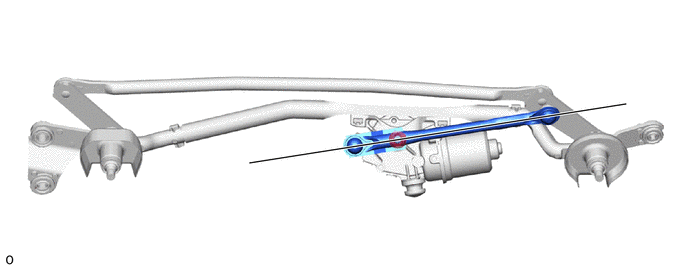
| *1 | No. 1 Windshield Wiper Link Rod | *2 | Windshield Wiper Motor Assembly Shaft |
| *3 | Windshield Wiper Motor Crank Pivot | - | - |
| *a | Straight Line | - | - |
2.INSTALL WINDSHIELD WIPER MOTOR AND LINK ASSEMBLY
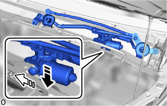
| *1 | Motor Grommet |

|
Install in this Direction (1) |

|
Install in this Direction (2) |
Attach the motor grommet and temporarily install the windshield wiper motor and link assembly as shown in the illustration.
- NOTICE:
-
Do not damage the vehicle with the front wiper motor and link assembly.
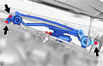

|
Bolt |

|
Connector |
Install the windshield wiper motor and link assembly with the 3 bolts in the order shown in the illustration.
- Torque:
- 5.5 N*m (56 kgf*cm, 49 in.*lbf)
Connect the connector.
55708
3.INSTALL COWL TOP VENTILATOR LOUVER SUB-ASSEMBLY
Temporarily install the cowl top ventilator louver sub-assembly as shown in the illustration.
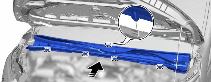
| *a | Positioning Guide | *b | Cutout |
|
|
Install in this Direction | - | - |
Align the positioning guide of the cowl top ventilator louver sub-assembly to the front window inner center moulding cutout.
Attach the guide.
Hold the rear of the cowl top ventilator louver sub-assembly down and attach the cowl top ventilator louver sub-assembly to the front window inner center moulding.
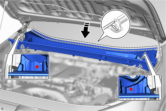
|
|
Install in this Direction | - | - |
- HINT:
- ·
Check that the cowl top ventilator louver sub-assembly does not lift up.
·Check that the positioning guide is not pinched by the front window inner center moulding.
Install the cowl top ventilator louver sub-assembly with the 2 clips.
Remove protective tape.
53808G
4.INSTALL FENDER APRON MUDGUARD SEAL SUB-ASSEMBLY LH
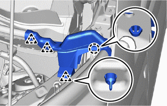
Attach the claw and clip to install the fender apron mudguard seal sub-assembly LH.
53807G
5.INSTALL FENDER APRON MUDGUARD SEAL SUB-ASSEMBLY RH
- HINT:
-
Use the same procedure described for the LH side.
53867H
6.INSTALL FRONT FENDER TO COWL SIDE SEAL LH
- HINT:
-
When installing the front fender to cowl side seal LH, heat the vehicle body and front fender to cowl side seal LH using a heat light.
- Standard:
Item Temperature Vehicle Body 40 to 60°C (104 to 140°F) Front Fender To Cowl Side Seal LH 20 to 30°C (68 to 86°F)
- CAUTION:
-
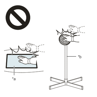 2.365,2 2.698,2 false 0.5,2.333 0.5,2.667 true 0.427,2.708 0.74,2.865 0.313,0.156 10 false *a 2.76,1.927 3.073,2.083 0.313,0.156 10 false *b
*a Heated Part *b Heat Light
- ·
Do not touch the heat light and heated parts.
·Touching the heat light may result in burns.
·Touching heated parts for a long time may result in burns.
- NOTICE:
-
Do not heat the vehicle body and front fender to cowl side seal LH excessively.
Clean the vehicle body surface.
Using a heat light, heat the vehicle body surface.
Remove any remaining double-sided tape from the vehicle body.
Wipe off any tape adhesive residue with cleaner.
- NOTICE:
- ·
Installing the front fender to cowl side seal LH with some double-sided tape remaining may cause poor adhesion. Perform this procedure until the tape is sufficiently removed.
·Make sure to use a cloth when removing. Using a screwdriver, etc., may cause damage and poor adhesion.
Using a heat light, heat the vehicle body and a new front fender to cowl side seal LH.
Remove the release paper from the front fender to cowl side seal LH.
- HINT:
-
After removing the release paper, keep the exposed adhesive free from foreign matter.
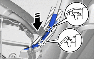
|
|
Install in this Direction |
Attach the clip as shown in the illustration.
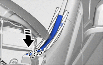
|
|
Install in this Direction |
Attach the claw as shown in the illustration.
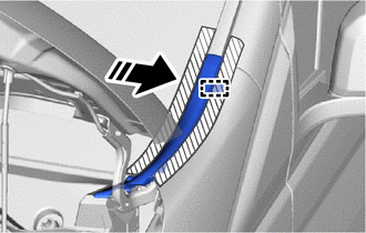
|
|
Install in this Direction |
Attach the guide in the direction indicated by the arrow as shown in the illustration.
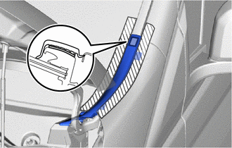
Attach the double-sided tape and install the front fender to cowl side seal LH as shown in the illustration.
Remove the protective tape.
53866J
7.INSTALL FRONT FENDER TO COWL SIDE SEAL RH
- HINT:
-
Use the same procedure described for the LH side.
8.INSTALL WINDSHIELD WIPER ARM AND BLADE ASSEMBLY RH
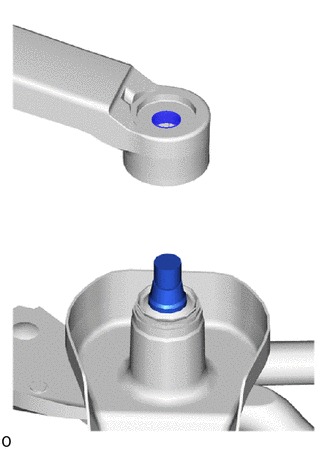
| *a | Windshield Wiper Arm Serrations |
| *b | Windshield Wiper Motor Assembly Pivot Serrations |
When reusing the windshield wiper arm and blade assembly RH:
Clean the windshield wiper arm serrations.
- NOTICE:
-
Do not grind the windshield wiper arm serrations.
When reusing the windshield wiper motor assembly:
Using a wire brush, clean the windshield wiper motor assembly pivot serrations.
- NOTICE:
-
Do not grind the windshield wiper motor assembly pivot serrations.
Turn the ignition switch to ON.
Operate the windshield wiper motor assembly and stop at the automatic stop (park) position.
Turn the ignition switch off.
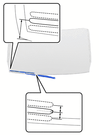
| *a | Ceramic Notch |
| *b | Windshield Glass Edge |
Align the ceramic notch of the windshield glass sub-assembly with the edge of the windshield wiper arm and blade assembly RH to install the windshield wiper arm and blade assembly RH with the nut.
- Torque:
- 26 N*m (265 kgf*cm, 19 ft.*lbf)
- Standard Clearance:
Area Measurement A 7.5 mm (0.295 in.) B 28 mm (1.102 in.)
- HINT:
- ·
After the windshield wiper motor assembly is stopped, check the automatic stop position after lifting the wiper blade 2 times.
·Hold the windshield wiper arm by hand while tightening the nut.
Turn the ignition switch to ON.
Operate the windshield wiper while spraying washer fluid onto the windshield glass. Make sure that the windshield wiper functions properly and the wiper does not come into contact with the vehicle body.
Turn the ignition switch off.
Raise the windshield wiper arm 2 times and check that the tip of the windshield wiper blade is within the range shown in the illustration.
9.INSTALL WINDSHIELD WIPER ARM AND BLADE ASSEMBLY LH
| *a | Windshield Wiper Arm Serrations |
| *b | Windshield Wiper Motor Assembly Pivot Serrations |
When reusing the windshield wiper arm and blade assembly LH:
Clean the windshield wiper arm serrations.
- NOTICE:
-
Do not grind the windshield wiper arm serrations.
When reusing the windshield wiper motor assembly:
Using a wire brush, clean the windshield wiper motor assembly pivot serrations.
- NOTICE:
-
Do not grind the windshield wiper motor assembly pivot serrations.
Turn the ignition switch to ON.
Operate the windshield wiper motor assembly and stop at the automatic stop (park) position.
Turn the ignition switch off.
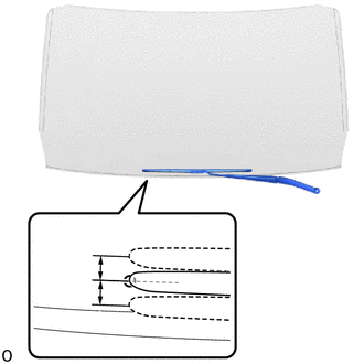
| *a | Ceramic Notch |
Align the ceramic notch of the windshield glass sub-assembly with the edge of the windshield wiper arm and blade assembly LH to install the windshield wiper arm and blade assembly LH with the nut.
- Torque:
- 26 N*m (265 kgf*cm, 19 ft.*lbf)
- Standard Clearance:
Area Measurement A 7.5 mm (0.295 in.)
- HINT:
- ·
After the windshield wiper motor assembly is stopped, check the automatic stop position after lifting the wiper blade 2 times.
·Hold the windshield wiper arm by hand while tightening the nut.
Turn the ignition switch to ON.
Operate the windshield wiper while spraying washer fluid onto the windshield glass. Make sure that the windshield wiper functions properly and the wiper does not come into contact with the vehicle body.
Turn the ignition switch off.
Raise the windshield wiper arm 2 times and check that the tip of the windshield wiper blade is within the range shown in the illustration.
85192
10.INSTALL WINDSHIELD WIPER ARM COVER
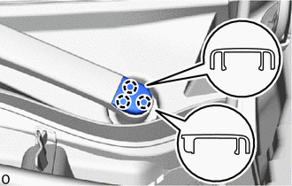
Attach the claw and install the windshield wiper arm cover.
- HINT:
-
Use the same procedure for the RH and LH sides.