AC60E AUTOMATIC TRANSMISSION / TRANSAXLE AUTOMATIC TRANSMISSION SYSTEM(for 7GR-FKS) P280713 Pressure Control Solenoid "G" Circuit Open
DESCRIPTION
Changing from 1st to 6th is performed by the ECM turning shift solenoid valves SL1, SL2, SL3 and SL4 on and off. If an open or short circuit occurs in any of the shift solenoid valves, the ECM controls the remaining normal shift solenoid valves to allow the vehicle to be operated.
| DTC No. | Detection Item | DTC Detection Condition | Trouble Area | MIL | Memory | Note |
|---|---|---|---|---|---|---|
| P280713 | Pressure Control Solenoid "G" Circuit Open | An open or short circuit (output signal duty is 0% or 100%) is detected by the ECM in the shift solenoid valve SL4 circuit while driving and shifting gears (SL4 output signal duty is more than 0% and less than 100% under normal conditions) (1 trip detection logic). | ·
Open or short in shift solenoid valve SL4 circuit ·
Shift solenoid valve SL4 ·
ECM |
Comes on | DTC stored | SAE Code:
P2810 |
MONITOR DESCRIPTION
This DTC indicates an open or short in the shift solenoid valve SL4 circuit. The ECM commands gear shifts by turning the shift solenoid valves on or off. When there is an open or short circuit in any of the shift solenoid valve circuits, the ECM detects the problem and illuminates the MIL and stores the DTC. The ECM also performs the fail-safe function and turns the other normal shift solenoid valves on or off. (In case of an open or short circuit, the ECM stops sending current to the circuit.)
While driving and shifting gears, if the ECM detects an open or short in the shift solenoid valve SL4 circuit, the ECM determines there is a malfunction.
CONFIRMATION DRIVING PATTERN
- CAUTION:
-
When performing the confirmation driving pattern, obey all speed limits and traffic laws.
- HINT:
-
After repairs have been completed, clear the DTCs and then check that the vehicle has returned to normal by performing the following All Readiness check procedure.
Connect the GTS to the DLC3.
Turn the ignition switch to ON and turn the GTS on.
Clear the DTCs (even if no DTCs are stored, perform the clear DTC procedure).
Turn the ignition switch off and wait for at least 30 seconds.
Turn the ignition switch to ON and turn the GTS on.
Start the engine.
Perform the D Position Shift Test in Road Test.
Stop the vehicle.
Enter the following menus: Powertrain / Transmission / Utility / All Readiness.
Input the DTC: P280713.
Check the DTC judgment result.
| GTS Display | Description |
|---|---|
| NORMAL | ·
DTC judgment completed ·
System normal |
| ABNORMAL | ·
DTC judgment completed ·
System abnormal |
| INCOMPLETE | ·
DTC judgment not completed ·
Perform driving pattern after confirming DTC enabling conditions |
| N/A | ·
Unable to perform DTC judgment ·
Number of DTCs which do not fulfill DTC preconditions has reached ECU memory limit |
- HINT:
- ·
If the judgment result shows NORMAL, the system is normal.
·If the judgment result shows ABNORMAL, the system has a malfunction.
·If the judgment result shows INCOMPLETE or N/A, perform the Confirmation Driving Pattern and check the DTC judgment result again.
WIRING DIAGRAM

CAUTION / NOTICE / HINT
- NOTICE:
-
Perform registration and/or initialization when parts related to the automatic transmission are replaced.
- HINT:
-
The following table shows normal operation of the shift solenoid valve SL4 when the shift lever is in D:
ECM commanded gear 1st 2nd 3rd 4th 5th 6th Shift solenoid valve SL4 OFF OFF ON OFF ON OFF
PROCEDURE
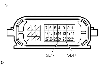
| *a | Component without harness connected
(Transmission Wire) |
Disconnect the transmission wire connector.
Measure the resistance according to the value(s) in the table below.
- Standard Resistance:
Tester Connection Condition Specified Condition 23 (SL4+) - 24 (SL4-) 20°C (68°F) 5.0 to 5.6 Ω 23 (SL4+) - Body ground Always 10 kΩ or higher 24 (SL4-) - Body ground Always 10 kΩ or higher
- Result:
Proceed to OK NG
OK
NG
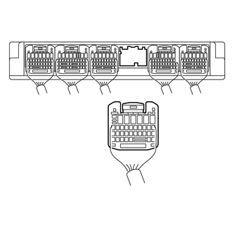
| *a | Rear view of wire harness connector
(to ECM) |
Disconnect the ECM connector.
Measure the resistance according to the value(s) in the table below.
- Standard Resistance:
Tester Connection Condition Specified Condition E4-8 (SL4+) - E4-7 (SL4-) 20°C (68°F) 5.0 to 5.6 Ω E4-8 (SL4+) - Body ground Always 10 kΩ or higher E4-7 (SL4-) - Body ground Always 10 kΩ or higher
- Result:
Proceed to OK NG
OK
NG
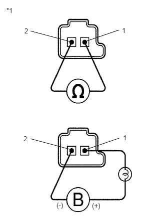
| *1 | Shift Solenoid Valve SL4 |
Remove shift solenoid valve SL4.
Measure the resistance according to the value(s) in the table below.
- Standard Resistance:
Tester Connection Condition Specified Condition 1 - 2 20°C (68°F) 5.0 to 5.6 Ω
Apply 12 V battery voltage to the shift solenoid valve and check that the valve moves and makes an operating noise.
- OK:
Measurement Condition Specified Condition ·Battery positive (+) with a 21 W bulb → Terminal 1
·Battery negative (-) → Terminal 2
Valve moves and makes an operating noise
- Result:
Proceed to OK NG
OK
NG