RM35X0E _56 Audio / Visual / Telematics _078377 AUDIO / VIDEO _0383454 AUDIO AND VISUAL SYSTEM(for Radio Receiver Type) J

AUDIO / VIDEO  AUDIO AND VISUAL SYSTEM(for Radio Receiver Type)  Microphone Circuit between Microphone and Radio Receiver  


DESCRIPTION

The radio receiver assembly, map light assembly and telephone microphone assembly are connected to each other using the microphone connection detection signal lines.

Using this circuit, the radio receiver assembly sends power to the map light assembly and telephone microphone assembly, and the map light assembly and telephone microphone assembly sends microphone signals to the radio receiver assembly.

WIRING DIAGRAM
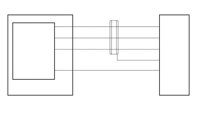
E402684
0.302,3.5 0.76,3.698 0.458,0.198 10 false a19 0.302,3.719 2.167,3.969 1.865,0.25 10 false Map Light Assembly 0.365,2.938 2.646,3.156 2.281,0.219 10 false Telephone Microphone Assembly 2.208,2.354 2.667,2.552 0.458,0.198 10 false SNS2 1.594,0.865 2.052,1.063 0.458,0.198 10 false MIC+ 1.625,1.302 2.083,1.5 0.458,0.198 10 false MIC- 1.5,1.708 2.063,1.906 0.563,0.198 10 false MACC 2.031,2.323 2.49,2.521 0.458,0.198 10 false 1 2.167,0.76 2.625,0.958 0.458,0.198 10 false MCO+ 2.208,1.177 2.667,1.375 0.458,0.198 10 false MCO- 2.177,1.594 2.719,1.792 0.542,0.198 10 false MACC 2.698,2.333 3.156,2.531 0.458,0.198 10 false 11 2.698,0.771 3.156,0.969 0.458,0.198 10 false 9 2.688,1.146 3.146,1.344 0.458,0.198 10 false 10 2.719,1.573 3.177,1.771 0.458,0.198 10 false 8 2.042,1.573 2.5,1.771 0.458,0.198 10 false 4 2.021,1.177 2.479,1.375 0.458,0.198 10 false 2 2.01,0.771 2.469,0.969 0.458,0.198 10 false 3 5.583,0.781 6.042,0.979 0.458,0.198 10 false 5 5.531,1.177 5.99,1.375 0.458,0.198 10 false 19 5.583,1.573 6.042,1.771 0.458,0.198 10 false 4 5.583,2.344 6.042,2.542 0.458,0.198 10 false 6 5.542,1.979 6,2.177 0.458,0.198 10 false 18 1.521,2.479 2.083,2.677 0.563,0.198 10 false SNS2 5.854,0.865 6.313,1.063 0.458,0.198 10 false MIN+ 5.844,1.292 6.302,1.49 0.458,0.198 10 false MIN- 5.833,1.708 6.375,1.906 0.542,0.198 10 false MACC 5.833,2.104 6.375,2.302 0.542,0.198 10 false SGND 5.844,2.448 6.302,2.646 0.458,0.198 10 false SNS2 5.781,3.5 6.24,3.698 0.458,0.198 10 false O12 5.792,3.698 6.813,4.156 1.021,0.458 10 false Radio Receiver Assembly 4.083,2.063 4.542,2.26 0.458,0.198 10 false * 0.302,4.198 2.167,4.448 1.865,0.25 10 false *: Shielded

PROCEDURE

1.CHECK HARNESS AND CONNECTOR (RADIO RECEIVER ASSEMBLY - MAP LIGHT ASSEMBLY)
a.

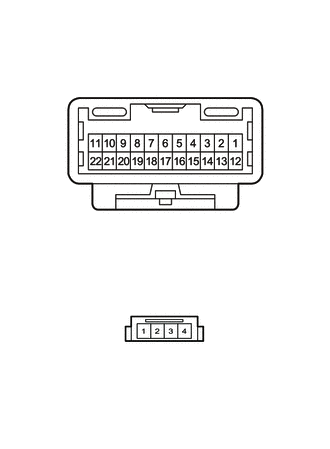
Disconnect the O12 radio receiver assembly connector.


b.

Disconnect the a19 map light assembly connector.


c.

Measure the resistance according to the value(s) in the table below.

Standard Resistance:
Tester Connection Condition Specified Condition
O12-4 (MACC) - a19-8 (MACC) Always Below 1 Ω
O12-5 (MIN+) - a19-9 (MCO+) Always Below 1 Ω
O12-6 (SNS2) - a19-11 (SNS2) Always Below 1 Ω
O12-19 (MIN-) - a19-10 (MCO-) Always Below 1 Ω
O12-18 (SGND) - Body ground Always 10 kΩ or higher
O12-4 (MACC) - Body ground Always 10 kΩ or higher
O12-5 (MIN+) - Body ground Always 10 kΩ or higher
O12-6 (SNS2) - Body ground Always 10 kΩ or higher
O12-19 (MIN-) - Body ground Always 10 kΩ or higher


Result:
Proceed to
OK
NG


OK

2.CHECK RADIO RECEIVER ASSEMBLY

NG

REPAIR OR REPLACE HARNESS OR CONNECTOR

2.CHECK RADIO RECEIVER ASSEMBLY
a.
E237416
1.448,0.448 1.865,0.677 0.417,0.229 2.25,1.771 2.719,0.865 true 2.219,2 2.5,2.667 true 1.333,2.615 2.052,1.979 true 0.083,0.094 0.396,0.292 0.313,0.198 10 false *a 1.51,0.479 1.823,0.677 0.313,0.198 10 false O12 2.781,0.719 3.281,0.948 0.5,0.229 10 false MACC 2.542,2.594 3.01,2.771 0.469,0.177 10 false SGND 1,2.521 1.333,2.76 0.333,0.24 10 false MIN-
*a Component with harness connected
(Radio Receiver Assembly)


Remove the radio receiver assembly with its connector still connected.

Click hereAudio / Visual / Telematics>AUDIO / VIDEO>RADIO RECEIVER>REMOVAL


b.

Measure the voltage according to the value(s) in the table below.

Standard Voltage:
Tester Connection Switch Condition Specified Condition
O12-4 (MACC) - Body ground Ignition switch ACC 4 to 6 V


c.

Measure the resistance according to the value(s) in the table below.

Standard Resistance:
Tester Connection Condition Specified Condition
O12-18 (SGND) - Body ground Always Below 1 Ω
O12-19 (MIN-) - Body ground Always Below 1 Ω


Result:
Proceed to
OK
NG


OK

3.INSPECT MAP LIGHT ASSEMBLY

NG

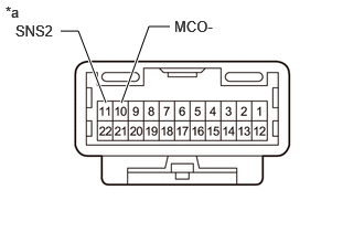
3.INSPECT MAP LIGHT ASSEMBLY
a.
E408104C02
0.573,0.292 0.74,0.292 0.74,0.292 1,0.969 true 1.604,0.25 1.406,0.25 1.406,0.25 1.146,0.969 true 0.146,0.208 0.76,0.406 0.615,0.198 10 false SNS2 1.646,0.167 2.26,0.365 0.615,0.198 10 false MCO- 0.052,0.031 0.667,0.229 0.615,0.198 10 false *a
*a Component without harness connected
(Map Light Assembly)


Remove the map light assembly.

Click hereVehicle Interior>LIGHTING (INT)>PERSONAL LIGHT>REMOVAL


b.

Measure the resistance according to the value(s) in the table below.

Standard Resistance:
Tester Connection Condition Specified Condition
11 (SNS2) - 10 (MCO-) Always Below 1 Ω


Result:
Proceed to
OK
NG


OK

4.CHECK MAP LIGHT ASSEMBLY (OUTPUT TO RADIO RECEIVER ASSEMBLY)

NG

7.INSPECT MAP LIGHT ASSEMBLY
4.CHECK MAP LIGHT ASSEMBLY (OUTPUT TO RADIO RECEIVER ASSEMBLY)
a.
E412458
1.542,0.344 1.917,0.594 0.375,0.25 1.063,1.198 0.708,0.427 0.708,0.427 0.531,0.427 true 1.177,1.198 2.281,0.469 2.281,0.469 2.49,0.469 true 2.552,0.385 3.167,0.583 0.615,0.198 10 false MCO+ 0.115,0.344 0.729,0.542 0.615,0.198 10 false MCO- 1.594,0.375 2.208,0.573 0.615,0.198 10 false a19 2.813,3.438 3.427,3.635 0.615,0.198 10 false GND 0.135,0.094 0.75,0.292 0.615,0.198 10 false *a
*a Component with harness connected
(Map Light Assembly)


Remove the map light assembly with the connector(s) still connected.

Click hereVehicle Interior>LIGHTING (INT)>PERSONAL LIGHT>REMOVAL


b.

Turn the ignition switch to ACC.


c.

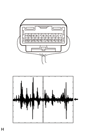
Connect an oscilloscope to terminals 9 (MCO+) and 10 (MCO-) of the a19 map light assembly connector.


d.

Check the signal waveform according to the condition(s) in the table below.

Item Condition
Measurement terminal a19-9 (MCO+) - a19-10 (MCO-)
Tool setting 50 mV/DIV., 500 ms/DIV.
Vehicle condition
1.

Turn the ignition switch to ACC.

2.

Sound is input to the map light assembly when the user is closer than 125 mm from the map light assembly sound holes.


OK:

The waveform is similar to that shown in the illustration.


HINT:

The oscilloscope waveform shown in the illustration is an example for reference only.


Result:
Proceed to
OK
NG


OK

NG

5.INSPECT MAP LIGHT ASSEMBLY

b.

Disconnect the A telephone microphone assembly connector.

c.
E408103
1.458,0.396 1.844,0.646 0.385,0.25 1.5,2.813 1.896,3.063 0.396,0.25 1.135,1.406 0.75,0.844 0.75,0.844 0.604,0.844 true 1.292,1.406 1.604,0.823 1.604,0.823 1.76,0.823 true 1.656,3.479 1.406,3.896 1.406,3.896 1.26,3.896 true 1.771,3.49 2.063,3.906 2.063,3.906 2.219,3.906 true 0.156,0.25 0.469,0.448 0.313,0.198 10 false *a 1.823,0.729 2.323,0.948 0.5,0.219 10 false MCO+ 0.177,0.75 0.656,0.958 0.479,0.208 10 false MCO- 1.656,2.854 1.969,3.052 0.313,0.198 10 false A 1.542,0.448 2.021,0.656 0.479,0.208 10 false a19 0.885,3.833 1.385,4.052 0.5,0.219 10 false MIC- 2.271,3.833 2.771,4.052 0.5,0.219 10 false MIC+ 0.125,2.521 0.438,2.719 0.313,0.198 10 false *b
*a Component without harness connected
(Map Light Assembly [Wire Harness Side])
*b Component without harness connected
(Map Light Assembly [Telephone Microphone Assembly Side])


Measure the resistance according to the value(s) in the table below.

Standard Resistance:
Tester Connection Condition Specified Condition
a19-9 (MCO+) - A-3 (MIC+) Always Below 1 Ω
a19-10 (MCO-) - A-2 (MIC-) Always Below 1 Ω
a19-9 (MCO+) - a19-10 (MCO-) Always 10 kΩ or higher


Result:
Proceed to
OK
NG


OK

6.CHECK TELEPHONE MICROPHONE ASSEMBLY

NG

6.CHECK TELEPHONE MICROPHONE ASSEMBLY
a.

Replace the telephone microphone assembly with a new or known good one and check that the malfunction disappears.

Click hereAudio / Visual / Telematics>TELEMATICS>TELEPHONE MICROPHONE ASSEMBLY>REMOVAL

Result:
Proceed to
OK
NG


OK:

Malfunction disappears.


OK

END (TELEPHONE MICROPHONE ASSEMBLY IS DEFECTIVE)

NG

7.INSPECT MAP LIGHT ASSEMBLY

b.

Disconnect the A telephone microphone assembly connector.


c.
E408103
1.573,0.396 1.958,0.646 0.385,0.25 1.5,2.813 1.896,3.063 0.396,0.25 0.979,1.417 0.656,0.833 0.656,0.833 0.51,0.833 true 1.146,1.406 1.458,0.823 1.458,0.823 1.615,0.823 true 1.49,3.479 1.24,3.896 1.24,3.896 1.094,3.896 true 1.646,3.49 1.938,3.906 1.938,3.906 2.094,3.906 true 0.135,0.354 0.448,0.552 0.313,0.198 10 false *a 1.656,0.729 2.156,0.948 0.5,0.219 10 false MCO- 0.104,0.74 0.583,0.948 0.479,0.208 10 false SNS2 1.656,2.854 1.969,3.052 0.313,0.198 10 false A 1.635,0.448 2.115,0.656 0.479,0.208 10 false a19 2.167,3.813 2.667,4.031 0.5,0.219 10 false MIC- 0.698,3.823 1.198,4.042 0.5,0.219 10 false SNS2 0.177,2.719 0.49,2.917 0.313,0.198 10 false *b
*a Component without harness connected
(Map Light Assembly [Wire Harness Side])
*b Component without harness connected
(Map Light Assembly [Telephone Microphone Assembly Side])


Measure the resistance according to the value(s) in the table below.

Standard Resistance:
Tester Connection Condition Specified Condition
a19-10 (MCO-) - A-2 (MIC-) Always Below 1 Ω
a19-11 (SNS2) - A-1 (SNS2) Always Below 1 Ω
a19-10 (MCO-) - a19-11 (SNS2) Always 10 kΩ or higher


Result:
Proceed to
OK
NG


OK

NG