7GR-FKS ENGINE CONTROL SFI SYSTEM P001600 Crankshaft Position - Camshaft Position Correlation Bank 1 Sensor A P001800 Crankshaft Position - Camshaft Position Correlation Bank 2 Sensor A
DESCRIPTION
In the VVT (Variable Valve Timing) system, the appropriate intake valve open and close timing is controlled by the ECM. The ECM performs intake valve control by performing the following: 1) controlling the intake camshaft, camshaft timing oil control solenoid assembly, camshaft timing gear bolt (camshaft timing oil control valve assembly [for intake camshaft]) and operating the camshaft timing gear; and 2) changing the relative positions of the camshaft and crankshaft.
| DTC No. | Detection Item | DTC Detection Condition | Trouble Area | MIL | Memory | Note |
|---|---|---|---|---|---|---|
| P001600 | Crankshaft Position - Camshaft Position Correlation Bank 1 Sensor A | Deviation in the crankshaft position sensor signal and VVT sensor (for intake camshaft of bank 1) signal (2 trip detection logic). | ·
Valve timing ·
Camshaft timing oil control solenoid assembly (for intake camshaft of bank 1) ·
Camshaft timing gear bolt (camshaft timing oil control valve assembly [for intake camshaft of bank 1]) ·
Camshaft timing gear assembly (bank 1) ·
Oil control valve filter (for intake camshaft of bank 1) ·
ECM |
Comes on / Does not come on | DTC stored | SAE Code: P0016 |
| P001800 | Crankshaft Position - Camshaft Position Correlation Bank 2 Sensor A | Deviation in the crankshaft position sensor signal and VVT sensor (for intake camshaft of bank 2) signal (2 trip detection logic). | ·
Valve timing ·
Camshaft timing oil control solenoid assembly (for intake camshaft of bank 2) ·
Camshaft timing gear bolt (camshaft timing oil control valve assembly [for intake camshaft of bank 2]) ·
Camshaft timing gear assembly (bank 2) ·
Oil control valve filter (for intake camshaft of bank 2) ·
ECM |
Comes on / Does not come on | DTC stored | SAE Code: P0018 |
MONITOR DESCRIPTION
To monitor the correlation of the intake camshaft position and crankshaft position, the ECM checks the VVT learned value while the engine is idling. The VVT learned value is calibrated based on the camshaft position and crankshaft position. The intake valve timing is set to the neutral position while the engine is idling. If the VVT learned value is out of the specified range in consecutive driving cycles, the ECM illuminates the MIL and stores a DTC.
MONITOR STRATEGY
| Required Sensors/Components (Main) | Camshaft timing gear assembly |
| Required Sensors/Components (Related) | VVT sensor
Crankshaft position sensor |
| Frequency of Operation | Continuous |
TYPICAL ENABLING CONDITIONS
| Engine speed | 400 to 1000 rpm |
CONFIRMATION DRIVING PATTERN
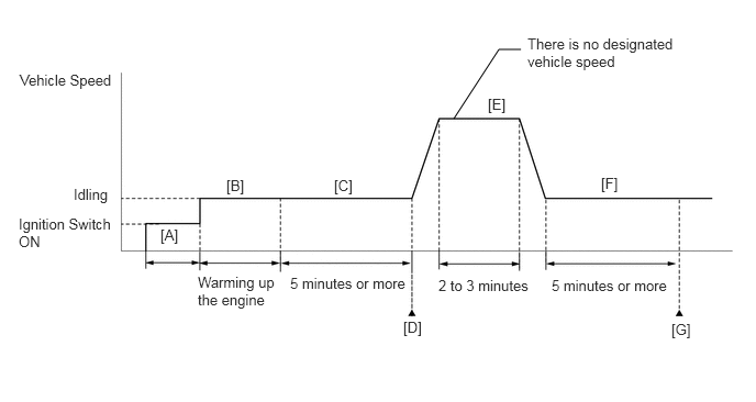
Connect the GTS to the DLC3.
Turn the ignition switch to ON.
Turn the GTS on.
Clear the DTCs (even if no DTCs are stored, perform the clear DTC procedure).
Turn the ignition switch off and wait for at least 30 seconds.
Turn the ignition switch to ON [A].
Turn the GTS on.
Start the engine and warm it up until the engine coolant temperature reaches 75°C (167°F) or higher [B].
Idle the engine for 5 minutes or more [C].
Enter the following menus: Powertrain / Engine / Trouble Codes [D].
Read the pending DTCs.
- HINT:
- ·
If a pending DTC is output, the system is malfunctioning.
·If a pending DTC is not output, perform the following procedure.
Enter the following menus: Powertrain / Engine / Utility / All Readiness.
Input the DTC: P001600 or P001800.
Check the DTC judgment result.
| GTS Display | Description |
|---|---|
| NORMAL | ·
DTC judgment completed ·
System normal |
| ABNORMAL | ·
DTC judgment completed ·
System abnormal |
| INCOMPLETE | ·
DTC judgment not completed ·
Perform driving pattern after confirming DTC enabling conditions |
- HINT:
- ·
If the judgment result is NORMAL, the system is normal.
·If the judgment result is ABNORMAL, the system has a malfunction.
·If the judgment result is INCOMPLETE, perform steps [E] through [G].
Drive the vehicle for 2 to 3 minutes or more [E].
- CAUTION:
-
When performing the confirmation driving pattern, obey all speed limits and traffic laws.
Idle the engine for 5 minutes or more [F].
Enter the following menus: Powertrain / Engine / Trouble Codes [G].
Read the pending DTCs.
- HINT:
- ·
If a pending DTC is output, the system is malfunctioning.
·If a pending DTC is not output, perform the following procedure.
Check the DTC judgment result.
- HINT:
- ·
If the judgment result is NORMAL, the system is normal.
·If the judgment result is ABNORMAL, the system has a malfunction.
CAUTION / NOTICE / HINT
- HINT:
- ·
Bank 1 refers to the bank that includes the No. 1 cylinder*.
*: The No. 1 cylinder is the cylinder which is farthest from the transmission.
·Bank 2 refers to the bank that does not include the No. 1 cylinder.
·The monitor for this DTC detects when the timing chain is shifted by one tooth or more.
·Read Freeze Frame Data using the GTS. The ECM records vehicle and driving condition information as Freeze Frame Data the moment a DTC is stored. When troubleshooting, Freeze Frame Data can help determine if the vehicle was moving or stationary, if the engine was warmed up or not, if the air fuel ratio was lean or rich, and other data from the time the malfunction occurred.
PROCEDURE
Start the engine.
Check for abnormal noise (rattling sounds) from the camshaft timing gear assembly with the engine idling.
- Result:
Result Proceed to Abnormal noise (rattling sound) from the camshaft timing gear assembly is heard. A Abnormal noise (rattling sound) from the camshaft timing gear assembly is not heard. B
- HINT:
- ·
As the engine speed increases, the camshaft timing gear assembly lock pins will release and the abnormal noise (rattling sound) will disappear.
·Perform "Inspection After Repair" after replacing the camshaft timing gear assembly.
A
B
Connect the GTS to the DLC3.
Turn the ignition switch to ON.
Turn the GTS on.
Enter the following menus: Powertrain / Engine / Trouble Codes.
Read the DTCs.
- Powertrain > Engine > Trouble Codes
- 50001 372
- Result:
Result Proceed to DTC P001600 or P001800 is output A DTC P001600 or P001800 and other DTCs are output B
- HINT:
-
If any DTCs other than P001600 or P001800 are output, troubleshoot those DTCs first.
A
B
- HINT:
-
If the VVT system can be operated through the Active Test, it can be assumed that the VVT system is operating normally.
Connect the GTS to the DLC3.
Start the engine.
Turn the GTS on.
Enter the following menus: Powertrain / Engine / Active Test / Control the Intake VVT OCV Duty Ratio Bank 1 or Control the Intake VVT OCV Duty Ratio Bank 2 / Data List / Intake VVT Change Angle Bank 1 or Intake VVT Change Angle Bank 2.
- Powertrain > Engine > Active Test
-
Active Test Display Control the Intake VVT OCV Duty Ratio Bank 1 -
Data List Display Intake VVT Change Angle Bank 1 - 50004 372 4 397
- Powertrain > Engine > Active Test
-
Active Test Display Control the Intake VVT OCV Duty Ratio Bank 2 -
Data List Display Intake VVT Change Angle Bank 2 - 50004 372 45 469
Perform the Active Test. Check that the displacement angle varies.
- OK:
Displacement angle varies.
- Result:
Proceed to OK NG
OK
NG
Check for mechanical malfunctions that affect the valve timing, such as a jumped tooth or stretching of the timing chain.
- HINT:
-
Perform "Inspection After Repair" after repairing or replacing the engine mechanical system.
- Result:
Proceed to OK NG
OK
NG
Inspect the camshaft timing oil control solenoid assembly (for intake camshaft).
- Result:
Proceed to OK NG
OK
NG
Inspect the camshaft timing gear bolt (camshaft timing oil control valve assembly [for intake camshaft]).
- Result:
Proceed to OK NG
OK
NG
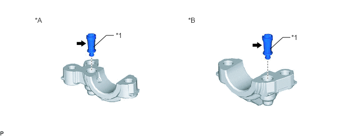
| *A | for Intake Camshaft of Bank 1 | *B | for Intake Camshaft of Bank 2 |
| *1 | Oil Control Valve Filter | - | - |
Remove the oil control valve filter (for intake camshaft of bank 1) or oil control valve filter (for intake camshaft of bank 2).
Check that the filter is not clogged.
- OK:
Filter is not clogged.
- Result:
Proceed to OK NG
OK
NG
Connect the GTS to the DLC3.
Turn the ignition switch to ON.
Turn the GTS on.
Clear the DTC.
- Powertrain > Engine > Clear DTCs
- 50002 372
Turn the ignition switch off and wait for at least 30 seconds.
- Result:
Proceed to NEXT
NEXT
Drive the vehicle in accordance with the driving pattern described in Confirmation Driving Pattern.
Enter the following menus: Powertrain / Engine / Trouble Codes / Pending.
Read the pending DTCs.
- Powertrain > Engine > Trouble Codes
- 50001 372
- Result:
Result Proceed to DTCs are not output A DTC P001600 or P001800 is output B
A
B
Replace the camshaft timing gear assembly.
- HINT:
-
Perform "Inspection After Repair" after replacing the camshaft timing gear assembly.
- Result:
Proceed to NEXT
NEXT
Connect the GTS to the DLC3.
Turn the ignition switch to ON.
Turn the GTS on.
Clear the DTC.
- Powertrain > Engine > Clear DTCs
- 50002 372
Turn the ignition switch off and wait for at least 30 seconds.
- Result:
Proceed to NEXT
NEXT
Drive the vehicle in accordance with the driving pattern described in Confirmation Driving Pattern.
Enter the following menus: Powertrain / Engine / Trouble Codes / Pending.
Read the pending DTCs.
- Powertrain > Engine > Trouble Codes
- 50001 372
- Result:
Result Proceed to DTCs are not output A DTC P001600 or P001800 is output B
A
B