7GR-FKS ENGINE CONTROL SFI SYSTEM P001100 Camshaft Position "A" - Timing Over-Advanced or System Performance Bank 1 P001200 Camshaft Position "A" - Timing Over-Retarded Bank 1 P002100 Camshaft Position "A" - Timing Over-Advanced or System Performance Bank 2 P002200 Camshaft Position "A" - Timing Over-Retarded Bank 2
DESCRIPTION
Refer to DTC P001013.
| DTC No. | Detection Item | DTC Detection Condition | Trouble Area | MIL | Memory | Note |
|---|---|---|---|---|---|---|
| P001100 | Camshaft Position "A" - Timing Over-Advanced or System Performance Bank 1 | Intake valve timing is stuck at a certain value when in the advance range (1 trip detection logic). | ·
Valve timing ·
Camshaft timing oil control solenoid assembly (for intake camshaft of bank 1) ·
Camshaft timing gear bolt (camshaft timing oil control valve assembly [for intake camshaft of bank 1]) ·
Camshaft timing gear assembly (bank 1) ·
Oil control valve filter (for intake camshaft of bank 1) ·
ECM |
Comes on | DTC stored | SAE Code: P0011 |
| P001200 | Camshaft Position "A" - Timing Over-Retarded Bank 1 | Intake valve timing is stuck at a certain value when in the retard range (1 trip detection logic). | ·
Valve timing ·
Camshaft timing oil control solenoid assembly (for intake camshaft of bank 1) ·
Camshaft timing gear bolt (camshaft timing oil control valve assembly [for intake camshaft of bank 1]) ·
Camshaft timing gear assembly (bank 1) ·
Oil control valve filter (for intake camshaft of bank 1) ·
ECM |
Comes on | DTC stored | SAE Code: P0012 |
| P002100 | Camshaft Position "A" - Timing Over-Advanced or System Performance Bank 2 | Intake valve timing is stuck at a certain value when in the advance range (1 trip detection logic). | ·
Valve timing ·
Camshaft timing oil control solenoid assembly (for intake camshaft of bank 2) ·
Camshaft timing gear bolt (camshaft timing oil control valve assembly [for intake camshaft of bank 2]) ·
Camshaft timing gear assembly (bank 2) ·
Oil control valve filter (for intake camshaft of bank 2) ·
ECM |
Comes on | DTC stored | SAE Code: P0021 |
| P002200 | Camshaft Position "A" - Timing Over-Retarded Bank 2 | Intake valve timing is stuck at a certain value when in the retard range (1 trip detection logic). | ·
Valve timing ·
Camshaft timing oil control solenoid assembly (for intake camshaft of bank 2) ·
Camshaft timing gear bolt (camshaft timing oil control valve assembly [for intake camshaft of bank 2]) ·
Camshaft timing gear assembly (bank 2) ·
Oil control valve filter (for intake camshaft of bank 2) ·
ECM |
Comes on | DTC stored | SAE Code: P0022 |
MONITOR DESCRIPTION
The ECM optimizes the intake valve timing using the Variable Valve Timing (VVT) system to control the intake camshaft. The VVT system includes the ECM, camshaft timing oil control solenoid assembly, camshaft timing gear bolt (camshaft timing oil control valve assembly [for intake camshaft]) and camshaft timing gear assembly. The ECM sends a target duty-cycle control signal to the camshaft timing oil control solenoid assembly. The camshaft timing gear bolt (camshaft timing oil control valve assembly [for intake camshaft]) is operated to control the oil pressure supplied to the camshaft timing gear assembly based on this signal. The camshaft timing gear assembly can advance or retard the intake camshaft.
If the difference between the target and actual intake valve timing is large, and changes in the actual intake valve timing are small, the ECM interprets this as the camshaft timing gear assembly stuck malfunction and stores a DTC.
Example:
A DTC is stored when the following conditions are met:
It takes 5 seconds or more to change the valve timing by 5°CA.
After the above condition is met, the camshaft timing oil control solenoid assembly is forcibly activated for 9.5 seconds.
These DTCs indicate that the camshaft timing gear assembly cannot operate properly due to a camshaft timing gear bolt (camshaft timing oil control valve assembly [for intake camshaft]) malfunction or the presence of foreign matter in the camshaft timing gear bolt (camshaft timing oil control valve assembly [for intake camshaft]).
MONITOR STRATEGY
| Required Sensors/Components (Main) | Camshaft timing oil control solenoid assembly
Camshaft timing gear bolt (camshaft timing oil control valve assembly [for intake camshaft]) Camshaft timing gear assembly |
| Required Sensors/Components (Related) | Crankshaft position sensor
VVT sensor Engine coolant temperature sensor |
| Frequency of Operation | Continuous |
CONFIRMATION DRIVING PATTERN
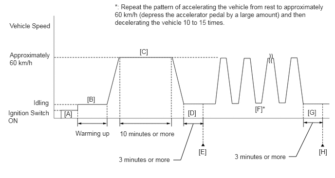
Connect the GTS to the DLC3.
Turn the ignition switch to ON.
Turn the GTS on.
Clear the DTCs (even if no DTCs are stored, perform the clear DTC procedure).
Turn the ignition switch off and wait for at least 30 seconds.
Turn the ignition switch to ON [A].
Turn the GTS on.
Start the engine and warm it up until the engine coolant temperature reaches 75°C (167°F) or higher [B].
Drive the vehicle at approximately 60 km/h (37 mph) for 10 minutes or more [C].
- CAUTION:
-
When performing the confirmation driving pattern, obey all speed limits and traffic laws.
Idle the engine for 3 minutes or more [D].
Enter the following menus: Powertrain / Engine / Trouble Codes [E].
Read the pending DTCs.
- HINT:
- ·
If a pending DTC is output, the system is malfunctioning.
·If a pending DTC is not output, perform the following procedure.
Enter the following menus: Powertrain / Engine / Utility / All Readiness.
Input the DTC: P001100, P001200, P002100 or P002200.
Check the DTC judgment result.
| GTS Display | Description |
|---|---|
| NORMAL | ·
DTC judgment completed ·
System normal |
| ABNORMAL | ·
DTC judgment completed ·
System abnormal |
| INCOMPLETE | ·
DTC judgment not completed ·
Perform driving pattern after confirming DTC enabling conditions |
- HINT:
- ·
If the judgment result is NORMAL, the system is normal.
·If the judgment result is ABNORMAL, the system has a malfunction.
·If the judgment result is INCOMPLETE, perform steps [F] through [H].
Repeat the pattern of accelerating the vehicle from rest to approximately 60 km/h (37 mph) and then decelerating the vehicle 10 to 15 times [F].
- CAUTION:
-
When performing the confirmation driving pattern, obey all speed limits and traffic laws.
- HINT:
-
Depress the accelerator pedal by a large amount.
Idle the engine for 3 minutes or more [G].
Enter the following menus: Powertrain / Engine / Trouble Codes [H].
Read the pending DTCs.
- HINT:
- ·
If a pending DTC is output, the system is malfunctioning.
·If a pending DTC is not output, perform the following procedure.
Check the DTC judgment result again.
- HINT:
- ·
If the judgment result is NORMAL, the system is normal.
·If the judgment result is ABNORMAL, the system has a malfunction.
WIRING DIAGRAM
Refer to DTC P001013.
CAUTION / NOTICE / HINT
- HINT:
Abnormal Bank Timing Over Advanced
(Valve timing is out of specified range)Timing Over Retarded
(Valve timing is out of specified range)Bank 1 P001100 P001200 Bank 2 P002100 P002200
- ·
If DTC P001100 or P001200 is output, check the VVT system (for intake camshaft of bank 1) circuit.
·If DTC P002100 or P002200 is output, check the VVT system (for intake camshaft of bank 2) circuit.
·Bank 1 refers to the bank that includes the No. 1 cylinder*.
*: The No. 1 cylinder is the cylinder which is farthest from the transmission.
·Bank 2 refers to the bank that does not include the No. 1 cylinder.
·DTC P001100, P001200, P002100 or P002200 may be stored when foreign matter in the engine oil is caught in some parts of the system. The DTC will remain stored even if the system returns to normal after a short time. That foreign matter may then be captured by the oil filter.
·Read Freeze Frame Data using the GTS. The ECM records vehicle and driving condition information as Freeze Frame Data the moment a DTC is stored. When troubleshooting, Freeze Frame Data can help determine if the vehicle was moving or stationary, if the engine was warmed up or not, if the air fuel ratio was lean or rich, and other data from the time the malfunction occurred.
PROCEDURE
Connect the GTS to the DLC3.
Turn the ignition switch to ON.
Turn the GTS on.
Enter the following menus: Powertrain / Engine / Trouble Codes.
Read the DTCs.
- Powertrain > Engine > Trouble Codes
- 50001 372
- Result:
Result Proceed to DTC P001100, P001200, P002100 or P002200 is output A DTC P001100, P001200, P002100 or P002200 and other DTCs are output B
- HINT:
-
If any DTCs other than P001100, P001200, P002100 or P002200 are output, troubleshoot those DTCs first.
A
B
Connect the GTS to the DLC3.
Start the engine.
Turn the GTS on.
Enter the following menus: Powertrain / Engine / Active Test / Control the Intake VVT OCV Duty Ratio Bank 1 or Control the Intake VVT OCV Duty Ratio Bank 2 / Data List / Intake VVT Change Angle Bank 1 or Intake VVT Change Angle Bank 2.
- Powertrain > Engine > Active Test
-
Active Test Display Control the Intake VVT OCV Duty Ratio Bank 1 -
Data List Display Intake VVT Change Angle Bank 1 - 50004 372 4 397
- Powertrain > Engine > Active Test
-
Active Test Display Control the Intake VVT OCV Duty Ratio Bank 2 -
Data List Display Intake VVT Change Angle Bank 2 - 50004 372 45 469
Read the Data List while performing the Active Test with the engine idling.
- OK:
GTS Operation Data List (Intake VVT Change Angle Bank 1 or Bank 2) -100% to 100% Varies by 70 DegFR or more
- Result:
Proceed to OK NG
OK
NG
Connect the GTS to the DLC3.
Turn the ignition switch to ON.
Turn the GTS on.
Clear the DTC.
- Powertrain > Engine > Clear DTCs
- 50002 372
Turn the ignition switch off and wait for at least 30 seconds.
- Result:
Proceed to NEXT
NEXT
Drive the vehicle in accordance with the driving pattern described in Confirmation Driving Pattern.
Enter the following menus: Powertrain / Engine / Trouble Codes.
Read the DTCs.
- Powertrain > Engine > Trouble Codes
- 50001 372
- Result:
Result Proceed to DTCs are not output A DTC P001100, P001200, P002100 or P002200 is output B
- HINT:
-
DTC P001100, P001200, P002100 or P002200 may be stored when foreign matter in the engine oil is caught in some parts of the system. The DTC will remain stored even if the system returns to normal after a short time. That foreign matter may then be captured by the oil filter.
A
B
Inspect the camshaft timing oil control solenoid assembly (for intake camshaft).
- Result:
Proceed to OK NG
OK
NG
Inspect the camshaft timing gear bolt (camshaft timing oil control valve assembly [for intake camshaft]).
- Result:
Proceed to OK NG
OK
NG
Remove the cylinder head cover sub-assembly and cylinder head cover sub-assembly LH.

| *a | Timing Mark | *b | TDC Timing Mark |
| *c | Groove | - | - |
Turn the crankshaft pulley and align its groove with the TDC timing mark of the timing chain cover.
Check that the timing marks of the camshaft timing gear assemblies and camshaft timing exhaust gear assemblies are aligned with the timing marks of the bearing cap as shown in the illustration.
- HINT:
-
If the timing marks are not as shown, turn the crankshaft one revolution clockwise.
- OK:
Timing marks on camshaft timing gear assemblies and camshaft timing exhaust gear assemblies are aligned as shown in the illustration.
- HINT:
-
If the result is not as specified, check for mechanical malfunctions that may have affected the valve timing, such as a jumped tooth or stretching of the timing chain.
- Result:
Proceed to OK NG
OK
NG
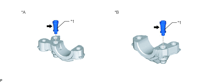
| *A | for Intake Camshaft of Bank 1 | *B | for Intake Camshaft of Bank 2 |
| *1 | Oil Control Valve Filter | - | - |
Remove the oil control valve filter (for intake camshaft of bank 1) or oil control valve filter (for intake camshaft of bank 2).
Check that the filter is not clogged.
- OK:
Filter is not clogged.
- Result:
Proceed to OK NG
OK
NG
Replace the camshaft timing oil control solenoid assembly (for intake camshaft).
- Result:
Proceed to NEXT
NEXT
Inspect the camshaft timing gear bolt (camshaft timing oil control valve assembly [for intake camshaft]).
- Result:
Proceed to OK NG
OK
NG
Replace the camshaft timing gear bolt (camshaft timing oil control valve assembly [for intake camshaft]).
- Result:
Proceed to NEXT
NEXT
Connect the GTS to the DLC3.
Start the engine.
Turn the GTS on.
Enter the following menus: Powertrain / Engine / Active Test / Control the Intake VVT OCV Duty Ratio Bank 1 or Control the Intake VVT OCV Duty Ratio Bank 2 / Data List / Intake VVT Change Angle Bank 1 or Intake VVT Change Angle Bank 2.
- Powertrain > Engine > Active Test
-
Active Test Display Control the Intake VVT OCV Duty Ratio Bank 1 -
Data List Display Intake VVT Change Angle Bank 1 - 50004 372 4 397
- Powertrain > Engine > Active Test
-
Active Test Display Control the Intake VVT OCV Duty Ratio Bank 2 -
Data List Display Intake VVT Change Angle Bank 2 - 50004 372 45 469
Read the Data List while performing the Active Test with the engine idling.
- OK:
GTS Operation Data List (Intake VVT Change Angle Bank 1 or Bank 2) -100% to 100% Varies by 70 DegFR or more
- Result:
Proceed to OK NG
OK
NG
Replace the camshaft timing gear assembly.
- HINT:
-
Perform "Inspection After Repair" after replacing the camshaft timing gear assembly.
- Result:
Proceed to NEXT
NEXT
Connect the GTS to the DLC3.
Turn the ignition switch to ON.
Turn the GTS on.
Clear the DTC.
- Powertrain > Engine > Clear DTCs
- 50002 372
Turn the ignition switch off and wait for at least 30 seconds.
- Result:
Proceed to NEXT
NEXT
Drive the vehicle in accordance with the driving pattern described in Confirmation Driving Pattern.
Enter the following menus: Powertrain / Engine / Trouble Codes.
Read the DTCs.
- Powertrain > Engine > Trouble Codes
- 50001 372
- Result:
Result Proceed to DTCs are not output A DTC P001100, P001200, P002100 or P002200 is output B
A
B