7GR-FKS ENGINE MECHANICAL CAMSHAFT INSTALLATION
PROCEDURE

 1.SET NO. 1 CYLINDER TO TDC/COMPRESSION
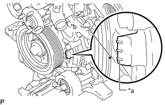
| *a | "0" Timing Mark |
| *b | Timing Mark (Cutout) |
Turn the crankshaft clockwise to align the timing mark (cutout) on the crankshaft pulley with the "0" timing mark on the timing chain cover assembly.
13050
2.SET CAMSHAFT TIMING GEAR ASSEMBLY (for Bank 2)
- HINT:
-
Perform "Inspection After Repairs" after replacing the camshaft timing gear assembly.
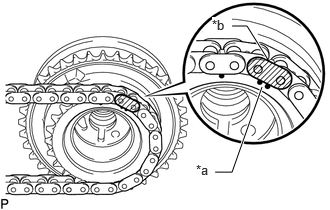
| *a | Timing Mark |
| *b | Mark Plate (Yellow) |
Align the mark plate (yellow) with the timing mark of the camshaft timing gear as shown in the illustration and install the No. 2 chain sub-assembly to the camshaft timing gear assembly.
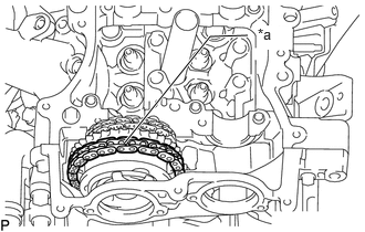
| *a | Place on camshaft timing gear |
Install the chain sub-assembly to the camshaft timing gear assembly, and then set the camshaft timing gear assembly to the camshaft housing sub-assembly LH.
- HINT:
- ·
Place the chain sub-assembly on the camshaft timing gear assembly but do not engage the teeth of the sprocket and the chain sub-assembly.
·Install the camshaft timing gear assembly so that the timing mark is facing upward.
13070A
3.SET CAMSHAFT TIMING EXHAUST GEAR ASSEMBLY (for Bank 2)
- HINT:
-
Perform "Inspection After Repairs" after replacing the camshaft timing exhaust gear assembly.
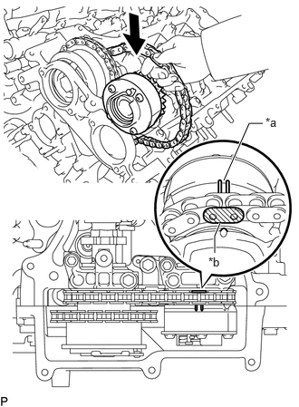
| *a | Timing Mark |
| *b | Mark Plate (Yellow) |
Align the mark plate (yellow) with the timing mark of the camshaft timing exhaust gear as shown in the illustration and install the No. 2 chain sub-assembly to the camshaft timing exhaust gear.
Set the camshaft timing exhaust gear assembly to the camshaft housing sub-assembly LH.
13560A
4.SET NO. 3 CHAIN TENSIONER ASSEMBLY
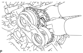
While lifting up the camshaft timing exhaust gear, pass the No. 3 chain tensioner assembly through the No. 2 chain sub-assembly and set it in place.
- NOTICE:
-
Temporarily set the No. 3 chain tensioner assembly only, do not install the bolt.
13053
5.INSTALL NO. 3 CAMSHAFT SUB-ASSEMBLY
- HINT:
-
Perform "Inspection After Repairs" after replacing the No. 3 camshaft sub-assembly.
Clean the camshaft housing sub-assembly LH and camshaft journals and apply engine oil to them.
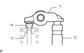
| *1 | Valve Rocker Arm |
| *2 | Valve Lash Adjuster Assembly |
| *3 | Valve Stem |
| *4 | Valve Stem Cap |
Make sure that the No. 1 valve rocker arm sub-assembly is installed as shown in the illustration.
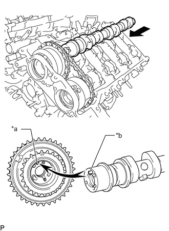
| *a | Pin Hole |
| *b | Straight Pin |
Put the camshaft timing gear assembly and No. 3 camshaft sub-assembly together by aligning the pin hole and straight pin.
Lightly press and turn the camshaft timing gear assembly against the No. 3 camshaft sub-assembly, and press harder after the pin enters the hole.
- NOTICE:
-
Securely insert the straight pin of the No. 3 camshaft sub-assembly into the pin hole of the camshaft timing gear assembly.
Check that there is no clearance between the camshaft timing gear assembly flange and No. 3 camshaft sub-assembly.
13054
6.INSTALL NO. 4 CAMSHAFT SUB-ASSEMBLY
- HINT:
-
Perform "Inspection After Repairs" after replacing the No. 4 camshaft sub-assembly.
Clean the camshaft housing sub-assembly LH and camshaft journals and apply engine oil to them.
| *1 | Valve Rocker Arm |
| *2 | Valve Lash Adjuster Assembly |
| *3 | Valve Stem |
| *4 | Valve Stem Cap |
Make sure that the No. 1 valve rocker arm sub-assembly is installed as shown in the illustration.
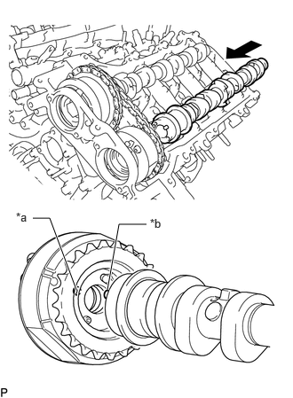
| *a | Pin Hole |
| *b | Straight Pin |
Put the camshaft timing exhaust gear assembly and No. 4 camshaft sub-assembly together by aligning the pin hole and straight pin.
Lightly press and turn the camshaft timing exhaust gear assembly against the No. 4 camshaft sub-assembly, and press harder after the pin enters the hole.
- NOTICE:
-
Securely insert the straight pin of the No. 4 camshaft sub-assembly into the pin hole of the camshaft timing exhaust gear assembly.
Check that there is no clearance between the camshaft timing exhaust gear assembly flange and No. 4 camshaft sub-assembly.
7.TEMPORARILY SET CAMSHAFT BEARING CAP (for Bank 2)
Clean the camshaft bearing caps and apply engine oil to them.
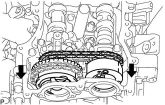
Slide the camshaft timing gear assembly and camshaft timing exhaust gear assembly toward the front of the vehicle.
- HINT:
-
To ensure there is sufficient space for installing the No. 3 camshaft bearing cap and No. 4 camshaft bearing cap, slide the camshaft timing gear assembly and camshaft timing exhaust gear assembly.
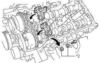
| *1 | Replacement Bolt |
| *2 | Replacement Washer |
| *3 | No. 3 Camshaft Bearing Cap |
| *4 | No. 4 Camshaft Bearing Cap |
Remove the replacement bolts and washers (No. 3 camshaft bearing cap side and No. 4 camshaft bearing cap side).
- NOTICE:
-
Do not remove any of the replacement bolts and washers other than those on the No. 3 camshaft bearing cap side and No. 4 camshaft bearing cap side.
Temporarily set the No. 3 camshaft bearing cap and No. 4 camshaft bearing cap.
- NOTICE:
- ·
Do not install the bolts of the No. 3 camshaft bearing cap and No. 4 camshaft bearing cap.
·Do not install any camshaft bearing caps other than the No. 3 camshaft bearing cap and No. 4 camshaft bearing cap.
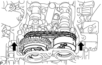
Slide the camshaft timing gear assembly and camshaft timing exhaust gear assembly toward the rear of the vehicle.
- NOTICE:
-
Securely insert the straight pins of the No. 3 camshaft sub-assembly and No. 4 camshaft sub-assembly into the pin holes of the camshaft timing gear assembly and camshaft timing exhaust gear assembly.
8.TEMPORARILY INSTALL CAMSHAFT TIMING GEAR BOLT (for Intake Side of Bank 2)
Check that there is no clearance between the camshaft timing gear assembly flange and No. 3 camshaft sub-assembly.
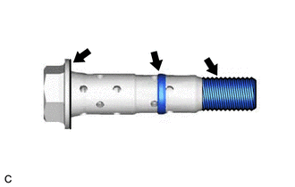
Apply engine oil to the areas of the camshaft timing gear bolt shown in the illustration.
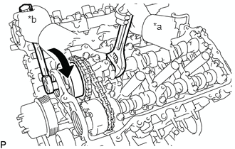
| *a | Hold |
| *b | Turn |
Use a wrench to hold the hexagonal portion of the No. 3 camshaft sub-assembly.
Temporarily install the camshaft timing gear bolt.
- Torque:
- 10 N*m (102 kgf*cm, 7 ft.*lbf)
- NOTICE:
- ·
Installing the camshaft timing gear bolt while there is external force applied to the camshaft timing gear assembly could result in damage to the engine, so make sure that the camshaft bearing cap is not installed when temporarily installing the camshaft timing gear bolt.
·Be careful not to damage the camshaft housing sub-assembly LH or spark plug tube with the wrench.
·Make sure that the flange part of the camshaft timing gear bolt is directly contacting the camshaft timing gear assembly.
9.TEMPORARILY INSTALL CAMSHAFT TIMING GEAR BOLT (for Exhaust Side of Bank 2)
Check that there is no clearance between the camshaft timing exhaust gear assembly flange and No. 4 camshaft sub-assembly.
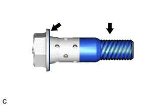
Apply engine oil to the areas of the camshaft timing gear bolt shown in the illustration.
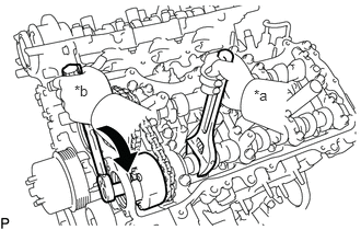
| *a | Hold |
| *b | Turn |
Use a wrench to hold the hexagonal portion of the No. 4 camshaft sub-assembly.
Temporarily install the camshaft timing gear bolt.
- Torque:
- 10 N*m (102 kgf*cm, 7 ft.*lbf)
- NOTICE:
- ·
Installing the camshaft timing gear bolt while there is external force applied to the camshaft timing exhaust gear assembly could result in damage to the engine, so make sure that the camshaft bearing cap is not installed when temporarily installing the camshaft timing gear bolt.
·Be careful not to damage the camshaft housing sub-assembly LH or spark plug tube with the wrench.
·Make sure that the flange part of the camshaft timing gear bolt is directly contacting the camshaft timing exhaust gear assembly.
10.INSTALL CAMSHAFT BEARING CAP (for Bank 2)
Clean the camshaft bearing caps and apply engine oil to them.
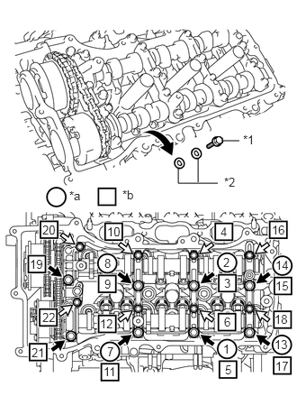
| *1 | Replacement Bolt |
| *2 | Replacement Washer |
| *a | Replacement Bolts and Washers Removal |
| *b | Part Installation |

|
Bolt A |

|
Bolt B |
Check the marks and numbers on the camshaft bearing caps, and then remove the replacement bolts and washers in the order shown in the illustration. Immediately after removing the replacement bolts and washers in the location for a bearing cap, install the bearing cap with the bolts in the order shown in the illustration.
- Torque:
- Bolt A : 28 N*m (286 kgf*cm, 21 ft.*lbf)
- Bolt B : 16 N*m (163 kgf*cm, 12 ft.*lbf)
- NOTICE:
- ·
Be sure to follow the numerical order when performing this procedure.
·Do not drop replacement bolts and washers into the cylinder head.
Check the torque of each bolt again.
11.TIGHTEN CAMSHAFT TIMING GEAR BOLT (for Intake Side of Bank 2)
| *a | Hold |
| *b | Turn |
Use a wrench to hold the hexagonal portion of the No. 3 camshaft sub-assembly.
Tighten the camshaft timing gear bolt.
- Torque:
- 95 N*m (969 kgf*cm, 70 ft.*lbf)
- NOTICE:
-
Be careful not to damage the camshaft housing sub-assembly LH or spark plug tube with the wrench.
12.TIGHTEN CAMSHAFT TIMING GEAR BOLT (for Exhaust Side of Bank 2)
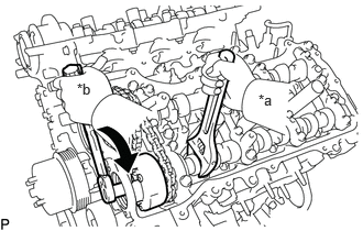
| *a | Hold |
| *b | Turn |
Use a wrench to hold the hexagonal portion of the No. 4 camshaft sub-assembly.
Tighten the camshaft timing gear bolt.
- Torque:
- 95 N*m (969 kgf*cm, 70 ft.*lbf)
- NOTICE:
-
Be careful not to damage the camshaft housing sub-assembly LH or spark plug tube with the wrench.
13560A
13.TIGHTEN NO. 3 CHAIN TENSIONER ASSEMBLY
Install the bolt to the No. 3 chain tensioner assembly.
Tighten the bolt.
- Torque:
- 21 N*m (214 kgf*cm, 15 ft.*lbf)
13506
14.CONNECT CHAIN SUB-ASSEMBLY (for Bank 2)
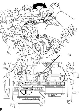
| *a | Paint Mark |
Align the paint marks on the camshaft timing gear assembly and chain sub-assembly and install the chain sub-assembly to the camshaft timing gear assembly.
- HINT:
-
If the paint marks are not aligned, align them by turning the camshaft slightly.
13050
15.SET CAMSHAFT TIMING GEAR ASSEMBLY (for Intake Side of Bank 1)
- HINT:
-
Perform "Inspection After Repairs" after replacing camshaft timing gear assembly.
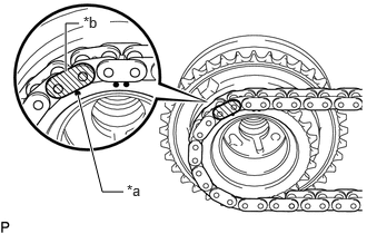
| *a | Timing Mark |
| *b | Mark Plate (Yellow) |
Align the mark plate (yellow) with the timing mark of the camshaft timing gear assembly as shown in the illustration and install the No. 2 chain sub-assembly to the camshaft timing gear assembly.
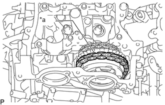
| *a | Place on camshaft timing gear |
Install the chain to the camshaft timing gear assembly, and then set the camshaft timing gear assembly to the camshaft housing sub-assembly RH.
- HINT:
- ·
Place the chain on the camshaft timing gear assembly but do not engage the teeth of the sprocket and the chain sub-assembly.
·Install the camshaft timing gear assembly so that the timing mark is facing upward.
13070A
16.SET CAMSHAFT TIMING EXHAUST GEAR ASSEMBLY (for Exhaust Side of Bank 1)
- HINT:
-
Perform "Inspection After Repairs" after replacing the camshaft exhaust gear assembly.
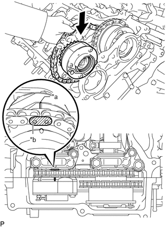
| *a | Timing Mark |
| *b | Mark Plate (Yellow) |
Align the mark plate (yellow) with the timing mark of the camshaft timing exhaust gear assembly as shown in the illustration and install the No. 2 chain sub-assembly to the camshaft timing exhaust gear assembly.
Set the camshaft timing exhaust gear assembly to the camshaft housing sub-assembly RH.
13550
17.TEMPORARILY SET NO. 2 CHAIN TENSIONER ASSEMBLY
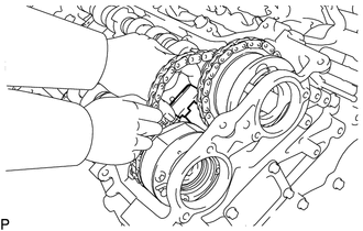
While lifting up the camshaft timing exhaust gear assembly, pass the No. 2 chain tensioner assembly through the No. 2 chain sub-assembly and set it in place.
- NOTICE:
-
Temporarily set the No. 2 chain tensioner assembly only, do not install the bolt.
13511
18.INSTALL CAMSHAFT
- HINT:
-
Perform "Inspection After Repairs" after replacing the camshaft.
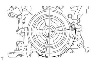
| *a | 5° to 10° |
Turn the crankshaft clockwise until it is in the position shown in the illustration so that the chain sub-assembly can be installed easily.
- HINT:
-
When turning the crankshaft, engine oil may spray out of the oil holes.
Clean the camshaft housing sub-assembly RH and camshaft journals and apply engine oil to them.
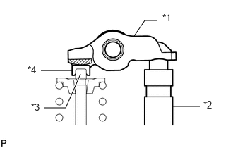
| *1 | Valve Rocker Arm |
| *2 | Valve Lash Adjuster Assembly |
| *3 | Valve Stem |
| *4 | Valve Stem Cap |
Make sure that the No. 1 valve rocker arm sub-assembly is installed as shown in the illustration.
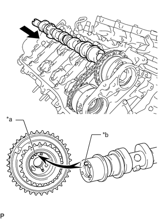
| *a | Pin Hole |
| *b | Straight Pin |
Put the camshaft timing gear assembly and camshaft together by aligning the pin hole and straight pin.
Lightly press and turn the camshaft timing gear assembly against the camshaft, and press harder after the pin enters the hole.
- NOTICE:
-
Securely insert the straight pin of the camshaft into the pin hole of the camshaft timing gear assembly.
Check that there is no clearance between the camshaft timing gear assembly flange and camshaft.
13512
19.INSTALL NO. 2 CAMSHAFT
- HINT:
-
Perform "Inspection After Repairs" after replacing the No. 2 camshaft.
Clean the camshaft housing sub-assembly RH and camshaft journals and apply engine oil to them.
| *1 | Valve Rocker Arm |
| *2 | Valve Lash Adjuster Assembly |
| *3 | Valve Stem |
| *4 | Valve Stem Cap |
Make sure that the No. 1 valve rocker arm sub-assembly is installed as shown in the illustration.
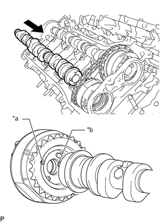
| *a | Pin Hole |
| *b | Straight Pin |
Put the camshaft timing exhaust gear assembly and No. 2 camshaft together by aligning the pin hole and straight pin.
Lightly press and turn the camshaft timing exhaust gear assembly against the No. 2 camshaft, and press harder after the pin enters the hole.
- NOTICE:
-
Securely insert the straight pin of the No. 2 camshaft into the pin hole of the camshaft timing exhaust gear assembly.
Check that there is no clearance between the camshaft timing exhaust gear assembly flange and No. 2 camshaft.
20.TEMPORARILY SET CAMSHAFT BEARING CAP (for Bank 1)
Clean the camshaft bearing caps and apply engine oil to them.
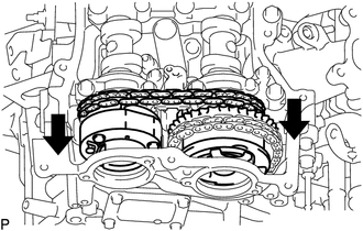
Slide the camshaft timing gear assembly and camshaft timing exhaust gear assembly toward the front of the vehicle.
- HINT:
-
To ensure there is sufficient space for installing the No. 1 camshaft bearing cap and No. 2 camshaft bearing cap, slide the camshaft timing gear assembly and camshaft timing exhaust gear assembly.
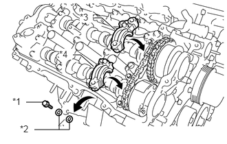
| *1 | Replacement Bolt |
| *2 | Replacement Washer |
| *3 | No. 1 Camshaft Bearing Cap |
| *4 | No. 2 Camshaft Bearing Cap |
Remove the replacement bolts and washers (No. 1 camshaft bearing cap side and No. 2 camshaft bearing cap side).
- NOTICE:
-
Do not remove any of the replacement bolts and washers other than those on the No. 1 camshaft bearing cap side and No. 2 camshaft bearing cap side.
Temporarily set the No. 1 camshaft bearing cap and No. 2 camshaft bearing cap.
- NOTICE:
- ·
Do not install the bolts of the No. 1 camshaft bearing cap and No. 2 camshaft bearing cap.
·Do not install any camshaft bearing caps other than the No. 1 camshaft bearing cap and No. 2 camshaft bearing cap.
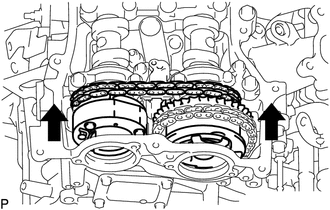
Slide the camshaft timing gear assembly and camshaft timing exhaust gear assembly toward the rear of the vehicle.
- NOTICE:
-
Securely insert the straight pins of the camshaft and No. 2 camshaft into the pin holes of the camshaft timing gear assembly and camshaft timing exhaust gear assembly.
21.TEMPORARILY INSTALL CAMSHAFT TIMING GEAR BOLT (for Intake Side of Bank 1)
Check that there is no clearance between the camshaft timing gear assembly flange and camshaft.
Apply engine oil to the areas of the camshaft timing gear bolt shown in the illustration.
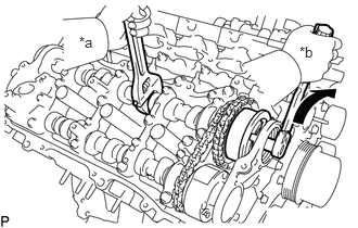
| *a | Hold |
| *b | Turn |
Use a wrench to hold the hexagonal portion of the camshaft.
Temporarily install the camshaft timing gear bolt.
- Torque:
- 10 N*m (102 kgf*cm, 7 ft.*lbf)
- NOTICE:
- ·
Installing the camshaft timing gear bolt while there is external force applied to the camshaft timing gear assembly could result in damage to the engine, so make sure that the camshaft bearing cap is not installed when temporarily installing the camshaft timing gear bolt.
·Be careful not to damage the camshaft housing sub-assembly RH or spark plug tube with the wrench.
·Make sure that the flange part of the camshaft timing gear bolt is directly contacting the camshaft timing gear assembly.
22.TEMPORARILY INSTALL CAMSHAFT TIMING GEAR BOLT (for Exhaust Side of Bank 1)
Check that there is no clearance between the camshaft timing exhaust gear assembly flange and No. 2 camshaft.
Apply engine oil to the areas of the camshaft timing gear bolt shown in the illustration.
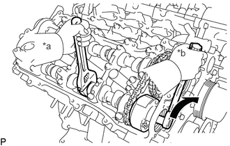
| *a | Hold |
| *b | Turn |
Use a wrench to hold the hexagonal portion of the No. 2 camshaft.
Temporarily install the camshaft timing gear bolt.
- Torque:
- 10 N*m (102 kgf*cm, 7 ft.*lbf)
- NOTICE:
- ·
Installing the camshaft timing gear bolt while there is external force applied to the camshaft timing exhaust gear assembly could result in damage to the engine, so make sure that the camshaft bearing cap is not installed when temporarily installing the camshaft timing gear bolt.
·Be careful not to damage the camshaft housing sub-assembly RH or spark plug tube with the wrench.
·Make sure that the flange part of the camshaft timing gear bolt is directly contacting the camshaft timing exhaust gear assembly.
23.INSTALL CAMSHAFT BEARING CAP (for Bank 1)
Clean the camshaft bearing caps and apply engine oil to them.
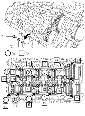
| *1 | Replacement Bolt |
| *2 | Replacement Washer |
| *a | Replacement Bolts and Washers Removal |
| *b | Part Installation |
|
|
Bolt A |
|
|
Bolt B |
Check the marks and numbers on the camshaft bearing caps, and then remove the replacement bolts and washers in the order shown in the illustration. Immediately after removing the replacement bolts and washers in the location for a bearing cap, install the bearing cap with the bolts in the order shown in the illustration.
- Torque:
- Bolt A : 28 N*m (286 kgf*cm, 21 ft.*lbf)
- Bolt B : 16 N*m (163 kgf*cm, 12 ft.*lbf)
- NOTICE:
- ·
Be sure to follow the numerical order when performing this procedure.
·Do not drop replacement bolts and washers into the cylinder head.
Check the torque of each bolt again.
24.TIGHTEN CAMSHAFT TIMING GEAR BOLT (for Intake Side of Bank 1)
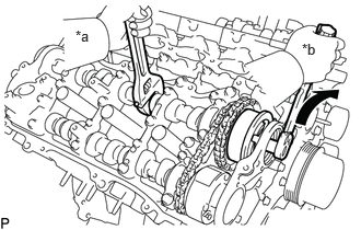
| *a | Hold |
| *b | Turn |
Use a wrench to hold the hexagonal portion of the camshaft.
Tighten the camshaft timing gear bolt.
- Torque:
- 95 N*m (969 kgf*cm, 70 ft.*lbf)
- NOTICE:
-
Be careful not to damage the camshaft housing sub-assembly RH or spark plug tube with the wrench.
25.TIGHTEN CAMSHAFT TIMING GEAR BOLT (for Exhaust Side of Bank 1)
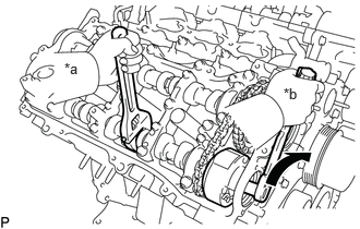
| *a | Hold |
| *b | Turn |
Use a wrench to hold the hexagonal portion of the No. 2 camshaft.
Tighten the camshaft timing gear bolt.
- Torque:
- 95 N*m (969 kgf*cm, 70 ft.*lbf)
- NOTICE:
-
Be careful not to damage the camshaft housing sub-assembly RH or spark plug tube with the wrench.
13550
26.TIGHTEN NO. 2 CHAIN TENSIONER ASSEMBLY
Install the bolt to the No. 2 chain tensioner assembly.
Tighten the bolt.
- Torque:
- 21 N*m (214 kgf*cm, 15 ft.*lbf)
13506
27.CONNECT CHAIN SUB-ASSEMBLY (for Bank 1)
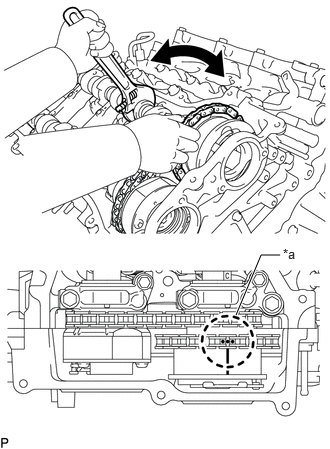
| *a | Paint Mark |
Align the paint marks on the camshaft timing gear assembly and chain sub-assembly and install the chain sub-assembly to the camshaft timing gear assembly.
- HINT:
-
If the paint marks are not aligned, align them by turning the camshaft slightly.
13540
28.INSTALL NO. 1 CHAIN TENSIONER ASSEMBLY
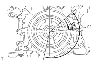
Turn the crankshaft counterclockwise 30° past the "0°" timing mark, and then turn it clockwise to align the notch with the "0°" timing mark.
Turn the crankshaft slightly to eliminate the slack in the chain sub-assembly.
- HINT:
-
Make sure there is some slack in the chain sub-assembly around the area where the chain tensioner is installed.
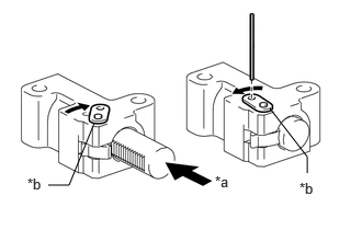
| *a | Push |
| *b | Stopper Plate |
While turning the stopper plate of the tensioner clockwise, push in the plunger of the tensioner as shown in the illustration.
While turning the stopper plate of the tensioner counterclockwise, insert a pin of 1.27 mm (0.0500 in.) into the holes in the stopper plate and tensioner to fix the stopper plate in place.
Install the No. 1 chain tensioner assembly with the 2 bolts.
- Torque:
- 10 N*m (102 kgf*cm, 7 ft.*lbf)
Remove the pin from the No. 1 chain tensioner assembly.
29.INSPECT VALVE TIMING
Check the camshaft timing marks.
- NOTICE:
- ·
Check each timing mark from a viewpoint directly in line with the center of the camshaft and the timing mark on each camshaft timing gear.
·If the timing marks are checked from any other viewpoint, the valve timing may appear misaligned.
Check that each camshaft timing mark is positioned as shown in the illustration.
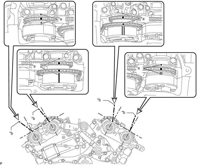
| *a | Timing Mark | *b | Timing Mark |
- HINT:
-
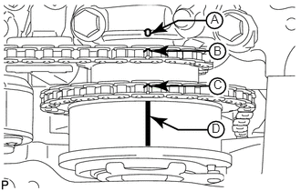 2.406,0.135 2.563,0.333 0.156,0.198 10 false A 2.438,0.5 2.594,0.698 0.156,0.198 10 false B 2.438,0.885 2.594,1.083 0.156,0.198 10 false C 2.417,1.385 2.573,1.583 0.156,0.198 10 false D
-
for Intake Camshaft:
-
Be sure to check mark A at the point when marks B, C and D are positioned in line. If the marks are checked from any other viewpoint, they cannot be checked correctly.
If the valve timing is misaligned, reinstall the timing chain.
Turn the crankshaft 2 revolutions, set the No. 1 cylinder to TDC/compression and check the timing marks again.
11324
30.INSTALL TIMING CHAIN COVER PLATE
Install a new gasket and the timing chain cover plate with the 4 bolts.
- Torque:
- 11 N*m (112 kgf*cm, 8 ft.*lbf)
29300
31.INSTALL VACUUM PUMP ASSEMBLY
87249B
32.CONNECT OUTLET HEATER WATER PIPE B
33.CONNECT VACUUM HOSE ASSEMBLY
11201
34.INSTALL CYLINDER HEAD COVER SUB-ASSEMBLY
11202
35.INSTALL CYLINDER HEAD COVER SUB-ASSEMBLY LH
15370B
36.INSTALL CAMSHAFT TIMING OIL CONTROL SOLENOID ASSEMBLY (for Intake Side of Bank 1)
15370B
37.INSTALL CAMSHAFT TIMING OIL CONTROL SOLENOID ASSEMBLY (for Exhaust Side of Bank 1)
15370C
38.INSTALL CAMSHAFT TIMING OIL CONTROL SOLENOID ASSEMBLY (for Intake Side of Bank 2)
15370C
39.INSTALL CAMSHAFT TIMING OIL CONTROL SOLENOID ASSEMBLY (for Exhaust Side of Bank 2)
11409
40.INSTALL ENGINE OIL LEVEL DIPSTICK GUIDE
19500
41.INSTALL IGNITION COIL ASSEMBLY
42.INSTALL WIRE HARNESS CLAMP BRACKET
for Cylinder Head Cover Sub-assembly Side:
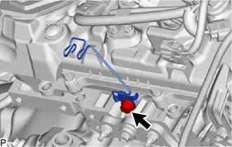
w/o Secondary Air Injection System:
Install the wire harness clamp bracket with the bolt.
- Torque:
- 31 N*m (316 kgf*cm, 23 ft.*lbf)
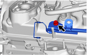
w/ Secondary Air Injection System:
Install the wire harness clamp bracket with the bolt.
- Torque:
- 13 N*m (133 kgf*cm, 10 ft.*lbf)
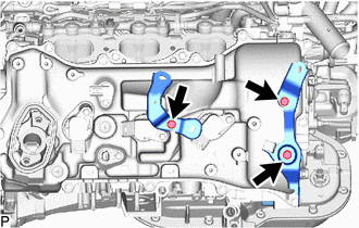
Install the 2 wire harness clamp brackets with the 3 bolts.
- Torque:
- 13 N*m (133 kgf*cm, 10 ft.*lbf)
for Cylinder Head Cover Sub-assembly LH Side:
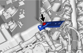
Install the wire harness clamp bracket with the bolt.
- Torque:
- 13 N*m (133 kgf*cm, 10 ft.*lbf)
43.CONNECT ENGINE WIRE
for Engine RH Side:
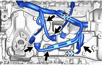
w/o Secondary Air Injection System:
Attach the 2 clamps and connect the 5 connectors.
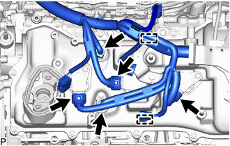
w/ Secondary Air Injection System:
Attach the 2 clamps and connect the 5 connectors.
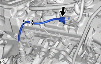
w/o Secondary Air Injection System:
Attach the clamp and connect the connector.
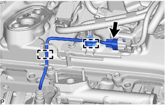
w/ Secondary Air Injection System:
Attach the 2 clamps and connect the connector.
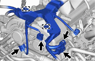
Attach the 2 clamps and connect the 4 connectors.
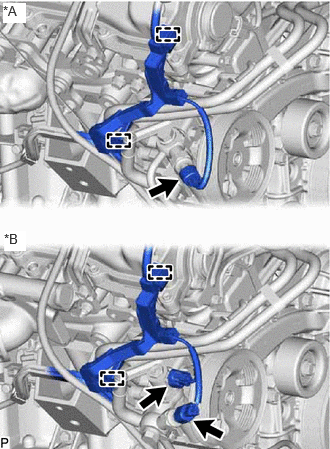
| *A | w/o Variable Flow Control Solenoid Valve |
| *B | w/ Variable Flow Control Solenoid Valve |
w/o Variable Flow Control Solenoid Valve:
Attach the 2 clamps and connect the connector.
w/ Variable Flow Control Solenoid Valve:
Attach the 2 clamps and connect the 2 connectors.
for Engine Rear Side:
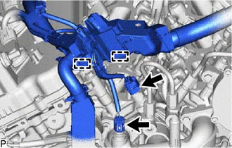
Attach the 2 clamps and connect the 2 connectors.
for Engine LH Side:
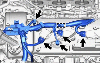
Attach the clamp and connect the 5 connectors.
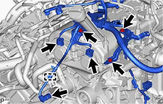
Connect the 3 wire harness clamp brackets with the 3 bolts.
- Torque:
- 13 N*m (133 kgf*cm, 10 ft.*lbf)
Attach the clamp and connect the 3 connectors.
82122A
44.CONNECT NO. 2 ENGINE WIRE
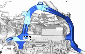
Attach the clamp.
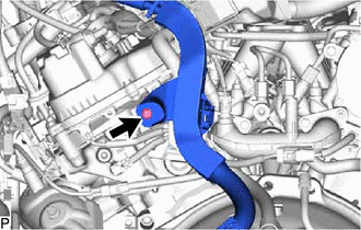
Connect the No. 2 engine wire with the bolt.
- Torque:
- 13 N*m (133 kgf*cm, 10 ft.*lbf)
17360G
45.INSTALL AIR TUBE ASSEMBLY (w/ Secondary Air Injection System)
46.INSTALL AIR SWITCHING VALVE ASSEMBLY (w/ Secondary Air Injection System)
17362
47.INSTALL NO. 2 AIR TUBE (w/ Secondary Air Injection System)
17361N
48.INSTALL NO. 1 AIR TUBE (w/ Secondary Air Injection System)
23100X
49.TEMPORARILY INSTALL FUEL (ENGINE ROOM SIDE) PUMP ASSEMBLY
23801P
50.TEMPORARILY INSTALL NO. 1 FUEL PIPE SUB-ASSEMBLY
23100X
51.INSTALL FUEL (ENGINE ROOM SIDE) PUMP ASSEMBLY
23801P
52.INSTALL NO. 1 FUEL PIPE SUB-ASSEMBLY
23903
53.INSTALL NO. 3 FUEL TUBE SUB-ASSEMBLY
17111
54.INSTALL INTAKE MANIFOLD
23800
55.INSTALL FUEL DELIVERY WITH SENSOR PIPE ASSEMBLY
23901
56.INSTALL FUEL TUBE SUB-ASSEMBLY AND NO. 2 FUEL TUBE SUB-ASSEMBLY
12262
57.INSTALL NO. 2 PCV HOSE
12261
58.INSTALL PCV HOSE
12601B
59.INSTALL NO. 1 ENGINE COVER SUB-ASSEMBLY (w/o Secondary Air Injection System)
12601B
60.INSTALL NO. 1 ENGINE COVER SUB-ASSEMBLY (w/o Secondary Air Injection System)
17190
61.INSTALL INTAKE AIR SURGE TANK ASSEMBLY
22267A
62.INSTALL THROTTLE BODY BRACKET
17125
63.INSTALL NO. 1 SURGE TANK STAY
17126
64.INSTALL NO. 2 SURGE TANK STAY
55701J
65.INSTALL OUTER COWL TOP PANEL SUB-ASSEMBLY
55738D
66.INSTALL NO. 2 HEATER AIR DUCT SPLASH SHIELD SEAL
85110
67.INSTALL WINDSHIELD WIPER MOTOR ASSEMBLY
16711
68.INSTALL FAN SHROUD
16572D
69.INSTALL NO. 2 RADIATOR HOSE
16571C
70.INSTALL NO. 1 RADIATOR HOSE
16470
71.INSTALL RADIATOR RESERVE TANK ASSEMBLY
44360
72.CONNECT VANE PUMP OIL RESERVOIR ASSEMBLY
17881
73.INSTALL AIR CLEANER ASSEMBLY WITH AIR CLEANER HOSE
17751
74.INSTALL NO. 1 AIR CLEANER INLET
47220D
75.CONNECT BRAKE MASTER CYLINDER RESERVOIR ASSEMBLY
76.CONNECT CABLE TO NEGATIVE BATTERY TERMINAL
77. INITIALIZATION AFTER RECONNECTING BATTERY TERMINAL
- HINT:
-
When disconnecting and reconnecting the battery, there is an automatic learning function that completes learning when the respective system is used.
78.BLEED CLUTCH PIPE LINE (for Manual Transmission)
79.INSPECT FOR BRAKE FLUID LEAK (for Manual Transmission)
80.CHECK FLUID LEVEL IN RESERVOIR (for Manual Transmission)
31301
81.INSPECT AND ADJUST CLUTCH PEDAL SUB-ASSEMBLY (for Manual Transmission)
82.ADD ENGINE OIL
83.ADD ENGINE COOLANT
84.INSPECT FOR FUEL LEAK
85.INSPECT FOR COOLANT LEAK
86.INSPECT FOR ENGINE OIL LEAK
87.INSPECT ENGINE COOLANT LEVEL IN RESERVOIR TANK
88.INSPECT IGNITION TIMING
11209
89.INSTALL V-BANK COVER SUB-ASSEMBLY
51405A
90.INSTALL NO. 1 ENGINE UNDER COVER SUB-ASSEMBLY
53106B
91.INSTALL RADIATOR COVER SUB-ASSEMBLY