RM35X0E _56 Audio / Visual / Telematics _078379 NAVIGATION / MULTI INFO DISPLAY _0380999 NAVIGATION SYSTEM J

NAVIGATION / MULTI INFO DISPLAY  NAVIGATION SYSTEM  Illumination Circuit  


DESCRIPTION

Power is supplied to the radio and display receiver assembly and steering pad switch assembly illumination when the light control switch is in the tail or head position.

WIRING DIAGRAM
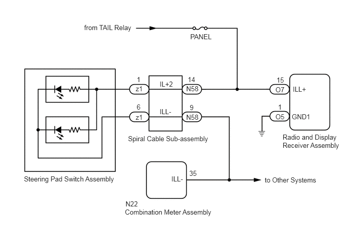
E408583E01
1.719,0.479 4.01,0.677 2.292,0.198 10 false from TAIL Relay 3.885,0.667 4.656,0.865 0.771,0.198 10 false PANEL 5.979,1.74 6.438,1.938 0.458,0.198 10 false ILL+ 3.26,2.198 3.719,2.396 0.458,0.198 10 false ILL- 3.26,1.635 3.719,1.833 0.458,0.198 10 false IL+2 0.49,3.573 4.771,3.771 4.281,0.198 10 false Steering Pad Switch Assembly 2.771,1.729 3.083,1.927 0.313,0.198 10 false z1 3.802,1.729 4.115,1.927 0.313,0.198 10 false N58 3.833,1.542 4.146,1.74 0.313,0.198 10 false 14 3.875,2.115 4.188,2.313 0.313,0.198 10 false 9 2.792,1.542 3.104,1.74 0.313,0.198 10 false 1 2.792,2.104 3.104,2.302 0.313,0.198 10 false 6 2.615,2.75 4.563,3.021 1.948,0.271 10 false Spiral Cable Sub-assembly 5.771,2.719 6.99,3.125 1.219,0.406 10 false Radio and Display Receiver Assembly 5.625,1.75 6.844,2.156 1.219,0.406 10 false O7 5.958,2.302 6.448,2.563 0.49,0.26 10 false GND1 5.646,1.552 5.958,1.75 0.313,0.198 10 false 15 5.677,2.104 5.99,2.302 0.313,0.198 10 false 1 5.625,2.302 6.844,2.708 1.219,0.406 10 false O5 2.771,2.313 3.083,2.51 0.313,0.198 10 false z1 3.802,2.313 4.115,2.51 0.313,0.198 10 false N58 2.552,4.25 4.5,4.521 1.948,0.271 10 false Combination Meter Assembly 2.563,4.083 4.51,4.354 1.948,0.271 10 false N22 3.865,3.458 4.177,3.656 0.313,0.198 10 false 35 3.5,3.573 3.958,3.771 0.458,0.198 10 false ILL- 5.406,3.594 6.729,3.865 1.323,0.271 10 false to Other Systems

CAUTION / NOTICE / HINT

NOTICE:
·

The vehicle is equipped with a Supplemental Restraint System (SRS) which includes components such as airbags. Before servicing (including removal or installation of parts), be sure to read the precaution for Supplemental Restraint System.

Click hereVehicle Interior>SUPPLEMENTAL RESTRAINT SYSTEMS>AIRBAG SYSTEM (for Type B)>PRECAUTION

·

Inspect the fuse for circuits related to this system before performing the following procedure.


PROCEDURE

1.CHECK ILLUMINATION
a.

Check if the illumination for the radio and display receiver assembly, steering pad switch assembly, heater control switch or others (hazard switch, transmission control switch, etc.) comes on when the light control switch is turned to the head or tail position.

Result:
Result Proceed to
Illumination comes on for all components except steering pad switch assembly. A
Illumination comes on for all components except radio and display receiver assembly. B
No illumination comes on (radio and display receiver assembly, hazard switch, heater control switch, etc.). C


A

2.CHECK HARNESS AND CONNECTOR (ILLUMINATION SIGNAL)

B

5.CHECK HARNESS AND CONNECTOR (ILLUMINATION SIGNAL)

C

2.CHECK HARNESS AND CONNECTOR (ILLUMINATION SIGNAL)
a.
E270420C53
1.5,0.25 1.875,0.479 0.375,0.229 2.24,1.5 2.313,1.917 2.313,1.917 2.479,1.917 true 2.531,1.833 2.917,2.021 0.385,0.188 10 false IL+2 0.083,0.104 0.396,0.302 0.313,0.198 10 false *a 1.573,0.281 1.885,0.479 0.313,0.198 10 false N58
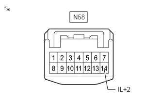
*a Front view of wire harness connector
(to Spiral Cable Sub-assembly)


Disconnect the spiral cable sub-assembly connector.


b.

Measure the voltage according to the value(s) in the table below.

Standard Voltage:
Tester Connection Condition Specified Condition
N58-14 (IL+2) - Body ground Light control switch in tail or head position 11 to 14 V


Result:
Proceed to
OK
NG


OK

3.INSPECT STEERING PAD SWITCH ASSEMBLY

NG

REPAIR OR REPLACE HARNESS OR CONNECTOR

5.CHECK HARNESS AND CONNECTOR (ILLUMINATION SIGNAL)
a.
E365519C13
0.708,0.938 1.083,1.24 0.375,0.302 2.281,0.948 2.656,1.25 0.375,0.302 1.927,1.813 1.719,0.635 1.719,0.635 1.552,0.635 true 1.51,2.448 1.344,2.448 1.344,2.448 1.208,1.927 true 2.406,1.021 2.865,1.219 0.458,0.198 10 false O5 0.813,1.01 1.271,1.208 0.458,0.198 10 false O7 1.146,0.552 1.594,0.802 0.448,0.25 10 false GND1 1.573,2.375 2.021,2.625 0.448,0.25 10 false ILL+ 0.156,0.146 0.604,0.396 0.448,0.25 10 false *a
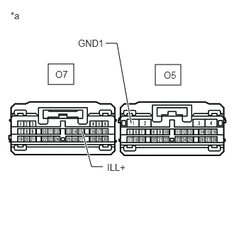
*a Front view of wire harness connector
(to Radio and Display Receiver Assembly)


Disconnect the radio and display receiver assembly connector.


b.

Measure the resistance according to the value(s) in the table below.

Standard Resistance:
Tester Connection Condition Specified Condition
O5-1 (GND1) - Body ground Always Below 1 Ω


c.

Measure the voltage according to the value(s) in the table below.

Standard Voltage:
Tester Connection Condition Specified Condition
O7-15 (ILL+) - Body ground Light control switch in tail or head position 11 to 14 V


Result:
Proceed to
OK
NG


OK

NG

REPAIR OR REPLACE HARNESS OR CONNECTOR