NAVIGATION / MULTI INFO DISPLAY NAVIGATION SYSTEM B153A GVIF Disconnected (from Extension Module to H/U)
DESCRIPTION
| DTC No. | Detection Item | DTC Detection Condition | Trouble Area |
|---|---|---|---|
| B153A | GVIF Disconnected (from Extension Module to H/U) | GVIF disconnected (from navigation ECU to radio and display receiver assembly) | ·
Navigation ECU ·
Radio and display receiver assembly ·
No. 1 navigation wire |
WIRING DIAGRAM
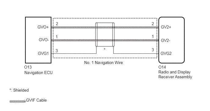
CAUTION / NOTICE / HINT
- NOTICE:
-
When replacing the radio and display receiver assembly or navigation ECU, always replace it with a new one. If a radio and display receiver assembly or navigation ECU which was installed to another vehicle is used, the following may occur:
- ·
A communication malfunction DTC may be stored.
·The radio and display receiver assembly or navigation ECU may not operate normally.
- HINT:
-
Depending on the parts that are replaced during vehicle inspection or maintenance, performing initialization, registration or calibration may be needed. Refer to Precaution for Navigation System.
PROCEDURE
Clear the DTCs.
- Body Electrical > Navigation System > Clear DTCs
- 50002 212
Recheck for DTCs and check that no DTCs are output.
- Body Electrical > Navigation System > Trouble Codes
- 50001 212
- OK:
No DTCs are output.
- Result:
Proceed to OK NG
OK
NG
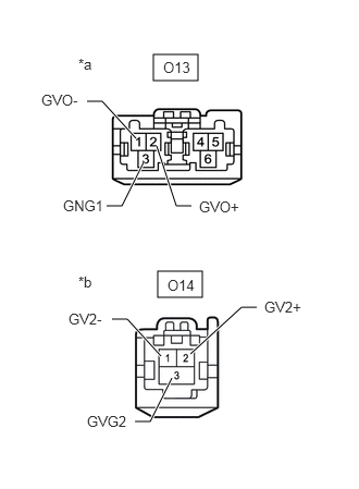
| *a | Front view of wire harness connector
(to Navigation ECU) |
| *b | Front view of wire harness connector
(to Radio and Display Receiver Assembly) |
Disconnect the O13 navigation ECU connector.
Disconnect the O14 radio and display receiver assembly connector.
Measure the resistance according to the value(s) in the table below.
- Standard Resistance:
Tester Connection Condition Specified Condition O13-1 (GVO-) - O14-1 (GV2-) Always Below 1 Ω O13-2 (GVO+) - O14-2 (GV2+) Always Below 1 Ω O13-3 (GVG1) - O14-3 (GVG2) Always Below 1 Ω
- Result:
Proceed to OK NG
OK
NG
- Result:
Proceed to NEXT
NEXT
Clear the DTCs.
- Body Electrical > Navigation System > Clear DTCs
- 50002 212
Recheck for DTCs and check that no DTCs are output.
- Body Electrical > Navigation System > Trouble Codes
- 50001 212
- OK:
No DTCs are output.
- Result:
Proceed to OK NG
OK
NG