TIRE PRESSURE MONITORING TIRE PRESSURE WARNING SYSTEM Tire Pressure Warning Reset Switch Circuit
DESCRIPTION
The switch circuit inside the combination meter assembly turns on and off according to the steering pad switch assembly operation.
WIRING DIAGRAM
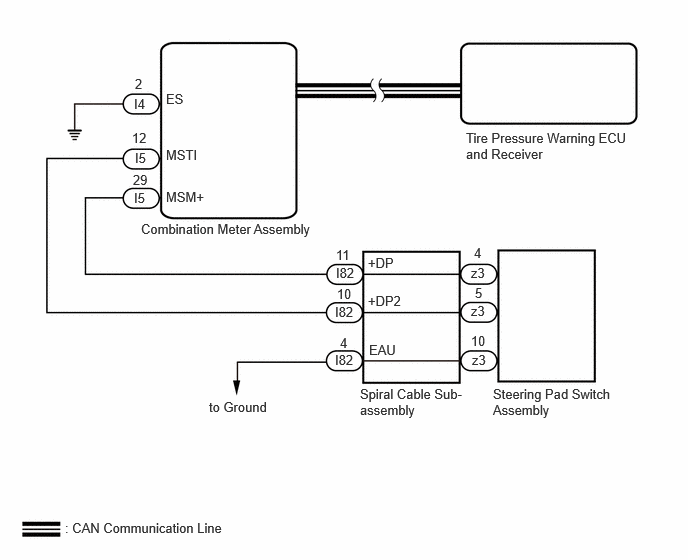
CAUTION / NOTICE / HINT
- NOTICE:
-
During the steering pad switch assembly check, check the precautions for the airbag system since the horn button assembly is removed during servicing. (installation/removal of parts, checks, replacement, etc.)
PROCEDURE
Check if CAN communication system DTCs are output.
for Gasoline Model: Click herePower Source / Network>NETWORKING>CAN COMMUNICATION SYSTEM (for Gasoline Model)>DIAGNOSIS SYSTEM202307,999999,_57,_104409,_0605911,RM100000002C081,
for HEV Model: Click herePower Source / Network>NETWORKING>CAN COMMUNICATION SYSTEM (for HEV Model)>DIAGNOSIS SYSTEM202307,999999,_57,_104409,_0606038,RM100000002C0LE,
- Result:
Result Proceed to DTCs are not output A DTCs are output B
A
B
for Gasoline Model: Click herePower Source / Network>NETWORKING>CAN COMMUNICATION SYSTEM (for Gasoline Model)>HOW TO PROCEED WITH TROUBLESHOOTING202307,202405,_57,_104409,_0605911,RM100000002C07Y,202405,999999,_57,_104409,_0605911,RM100000002NU3H,
for HEV Model: Click herePower Source / Network>NETWORKING>CAN COMMUNICATION SYSTEM (for HEV Model)>HOW TO PROCEED WITH TROUBLESHOOTING202307,999999,_57,_104409,_0606038,RM100000002C0LC,
- Result:
Proceed to OK NG
OK
NG
- Result:
Proceed to OK NG
OK
NG
Disconnect the I82 spiral cable sub-assembly connector.
Disconnect the I4 and I5 combination meter assembly connector.
Measure the resistance according to the value(s) in the table below.
- Standard Resistance:
Tester Connection Condition Specified Condition I82-11 (+DP) - I5-29 (MSM+) Always Below 1 Ω I82-11 (+DP) or I5-29 (MSM+) - Body ground Always 10 kΩ or higher I82-10 (+DP2) - I5-12 (MSTI) Always Below 1 Ω I82-10 (+DP2) or I5-12 (MSTI) - Body ground Always 10 kΩ or higher I4-2 (ES) - Body ground Always Below 1 Ω
- Result:
Proceed to OK NG
OK
NG