RM38T0EC _58 Vehicle Interior _115188 SUPPLEMENTAL RESTRAINT SYSTEMS _0510624 SPIRAL CABLE G

SUPPLEMENTAL RESTRAINT SYSTEMS  SPIRAL CABLE  INSPECTION  


PROCEDURE

Hide 84306 1.INSPECT SPIRAL CABLE SUB-ASSEMBLY

NOTICE:
·

Do not remove the steering sensor from the spiral cable sub-assembly when inspecting the spiral cable sub-assembly.

·

Remove the steering sensor from the spiral cable sub-assembly only when replacing the spiral cable sub-assembly.


a.

Visually check the spiral cable sub-assembly for defects.

i.

The defects are as follows:

·

Scratches

·

Small cracks

·

Dents

·

Chips

·

Cracks or other damage to the connector

OK:

No defects are found.


If any of the defects is found, replace the spiral cable sub-assembly with a new one.


b.

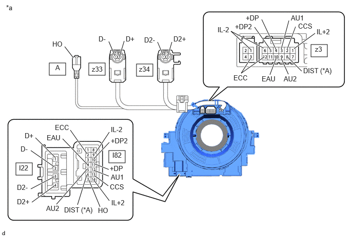
Check the spiral cable sub-assembly.

w/o Steering Heater
B625668C02
1.802,1.281 2.135,1.531 0.333,0.25 1,1.281 1.333,1.531 0.333,0.25 2.771,1.302 3.104,1.552 0.333,0.25 6.313,0.906 6.646,1.156 0.333,0.25 2.208,3.063 2.542,3.313 0.333,0.25 0.323,3.313 0.656,3.563 0.333,0.25 1.313,0.948 1.49,1.177 true 2.208,0.844 2.333,1.135 true 2.427,1.146 2.521,0.833 true 3.406,1.135 3.49,0.854 true 3.198,0.854 3.313,1.125 true 5.083,1 4.688,0.635 4.688,0.635 5.354,0.979 true 5.094,1.177 4.896,1.49 4.896,1.49 5.365,1.156 true 5.167,0.552 5.49,1.01 true 5.313,0.396 5.604,1.01 true 5.865,0.417 5.708,1 true 6,0.542 5.833,0.99 true 6.396,0.677 5.969,0.99 true 6.125,1.448 5.833,1.156 true 5.854,1.51 5.708,1.188 true 5.479,1.521 5.604,1.188 true 2.219,2.688 1.927,3.125 true 2.219,2.896 1.906,3.229 true 2.208,3.448 1.917,3.333 true 2.208,3.583 1.917,3.469 true 2.198,3.781 1.917,3.573 true 2.219,4.083 1.906,3.667 true 2.031,4.208 1.802,3.656 true 1.573,4.167 1.76,3.563 true 1.146,4.156 1.771,3.438 true 0.646,4.115 1.104,3.781 true 0.625,3.844 1.104,3.594 true 0.625,3.063 1.104,3.396 true 0.719,2.802 1.125,3.208 true 1.427,2.646 1.771,3.135 true 1.271,2.823 1.771,3.344 true 0.125,0.073 0.438,0.271 0.313,0.198 10 false *a 1.125,1.292 1.438,1.49 0.313,0.198 10 false A 1.865,1.323 2.177,1.521 0.313,0.198 10 false z33 2.823,1.323 3.135,1.521 0.313,0.198 10 false z34 1.063,0.813 1.375,1.01 0.313,0.198 10 false HO 2,0.708 2.313,0.906 0.313,0.198 10 false D- 0.5,2.677 0.813,2.875 0.313,0.198 10 false D+ 2.927,0.729 3.24,0.927 0.313,0.198 10 false D2- 3.521,0.708 3.875,0.906 0.354,0.198 10 false D2+ 4.74,1.5 5.177,1.667 0.438,0.167 10 false ECC 4.417,0.521 4.854,0.688 0.438,0.167 10 false IL-2 4.771,0.458 5.208,0.646 0.438,0.188 10 false +DP2 4.99,0.281 5.427,0.469 0.438,0.188 10 false +DP 5.906,0.281 6.344,0.469 0.438,0.188 10 false AU1 6.052,0.448 6.49,0.635 0.438,0.188 10 false CCS 6.427,0.563 6.865,0.75 0.438,0.188 10 false IL+2 6.396,0.917 6.708,1.115 0.313,0.198 10 false z3 6.156,1.354 6.875,1.583 0.719,0.229 10 false DIST (*A) 5.76,1.521 6.188,1.729 0.427,0.208 10 false AU2 5.313,1.521 5.74,1.729 0.427,0.208 10 false EAU 2.25,2.552 2.688,2.719 0.438,0.167 10 false IL-2 2.25,2.781 2.688,2.969 0.438,0.188 10 false +DP2 2.281,3.073 2.594,3.271 0.313,0.198 10 false I82 2.229,3.344 2.667,3.531 0.438,0.188 10 false +DP 2.25,3.521 2.688,3.708 0.438,0.188 10 false AU1 2.229,3.719 2.667,3.906 0.438,0.188 10 false CCS 2.26,4.042 2.698,4.208 0.438,0.167 10 false IL+2 1.99,4.198 2.427,4.365 0.438,0.167 10 false HO 1.302,4.188 1.938,4.396 0.635,0.208 10 false DIST (*A) 0.938,4.156 1.375,4.344 0.438,0.188 10 false AU2 0.344,4.021 0.698,4.219 0.354,0.198 10 false D2+ 0.344,3.729 0.656,3.927 0.313,0.198 10 false D2- 1.115,2.51 1.552,2.677 0.438,0.167 10 false ECC 0.948,2.719 1.375,2.927 0.427,0.208 10 false EAU 2.552,0.708 2.865,0.906 0.313,0.198 10 false D+ 0.417,2.948 0.729,3.146 0.313,0.198 10 false D- 0.385,3.333 0.698,3.531 0.313,0.198 10 false I22
*A w/ Lane Departure Alert System - -
*a Component without harness connected
(Spiral Cable Sub-assembly)
- -
V100144

Interlock - -


NOTICE:
·

When rotating the spiral cable sub-assembly, make sure to push on the interlock shown in the illustration to release the interlock mechanism.

·

As the spiral cable sub-assembly may break, do not rotate the spiral cable sub-assembly more than the specified amount.


i.

Set the spiral cable sub-assembly to the center position.

Click here


ii.

Measure the resistance between each terminal of the spiral cable sub-assembly according to the value(s) in the table below.


iii.

After setting the spiral cable sub-assembly to the center position, rotate the spiral cable sub-assembly 2.5 times clockwise, and measure the resistance according to the value(s) in the table below. Then rotate the spiral cable sub-assembly 5 times counterclockwise, and measure the resistance according to the value(s) in the table below.


iv.

After setting the spiral cable sub-assembly to the center position, rotate the spiral cable sub-assembly 2.5 times clockwise. Then while rotating the spiral cable sub-assembly 5 times counterclockwise, measure the resistance according to the value(s) in the table below.

Standard Resistance:
Tester Connection Condition Specified Condition
I82-2 (ECC) - z3-12 (ECC) Always 3 Ω or less
I82-4 (EAU) - z3-10 (EAU) Always 3 Ω or less
I82-5 (AU2) - z3-9 (AU2) Always 3 Ω or less
I82-6 (DIST) - z3-8 (DIST) Always 3 Ω or less
I82-7 (HO) - A (HO) Always 3 Ω or less
I82-9 (IL-2) - z3-6 (IL-2) Always 3 Ω or less
I82-10 (+DP2) - z3-5 (+DP2) Always 3 Ω or less
I82-11 (+DP) - z3-4 (+DP) Always 3 Ω or less
I82-12 (AU1) - z3-3 (AU1) Always 3 Ω or less
I82-13 (CCS) - z3-2 (CCS) Always 3 Ω or less
I82-14 (IL+2) - z3-1 (IL+2) Always 3 Ω or less
I22-1 (D+) - z33-2 (D+) Always Below 1 Ω
I22-2 (D-) - z33-1 (D-) Always Below 1 Ω
I22-3 (D2-) - z34-1 (D2-) Always Below 1 Ω
I22-4 (D2+) - z34-2 (D2+) Always Below 1 Ω


If the result is not as specified, replace the spiral cable sub-assembly.