FRONT SUSPENSION FRONT SHOCK ABSORBER INSTALLATION
CAUTION / NOTICE / HINT
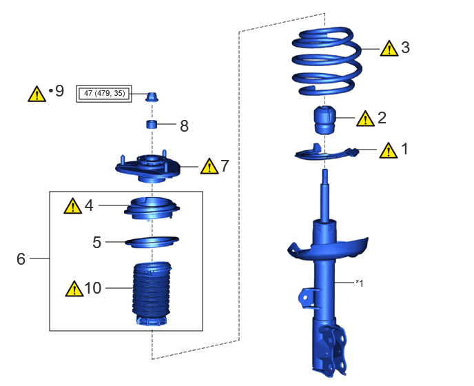
| Procedure | Part Name Code | 
|

|

|
|
|---|---|---|---|---|---|
| 1 | FRONT LOWER COIL SPRING INSULATOR | 48158C | ( 202307,999999,_53,_112966,_0502991,RM100000002C39Y_01_0007,) 202307,999999,_53,_112966,_0502991,RM100000002C39Y_01_0007,)
|
- | - |
| 2 | FRONT SPRING BUMPER | 48331C | (202307,999999,_53,_112966,_0502991,RM100000002C39Y_01_0008,)
|
- | - |
| 3 | FRONT COIL SPRING | 48132 | (202307,999999,_53,_112966,_0502991,RM100000002C39Y_01_0039,)
|
- | - |
| 4 | STRUT MOUNTING BEARING | 48619A | (202307,999999,_53,_112966,_0502991,RM100000002C39Y_01_0051,)
|
- | - |
| 5 | FRONT UPPER COIL SPRING INSULATOR | 48157C | - | - | - |
| 6 | STRUT MOUNTING BEARING WITH DUST COVER | - | - | - | - |
| 7 | FRONT SUSPENSION SUPPORT SUB-ASSEMBLY | 48609 | (202307,999999,_53,_112966,_0502991,RM100000002C39Y_01_0013,)
|
- | - |
| 8 | COLLAR | - | - | - | - |
| 9 | TEMPORARILY TIGHTEN FRONT SUPPORT TO FRONT SHOCK ABSORBER NUT | 48609E | (202307,999999,_53,_112966,_0502991,RM100000002C39Y_01_0043,)
|
- | - |
| 10 | FRONT NO. 1 SHOCK ABSORBER DUST COVER | 48559B | (202307,999999,_53,_112966,_0502991,RM100000002C39Y_01_0041,)
|
- | - |
| *1 | FRONT SHOCK ABSORBER ASSEMBLY | - | - |

|
Tightening torque for "Major areas involving basic vehicle performance such as moving/turning/stopping" : N*m (kgf*cm, ft.*lbf) | ● | Non-reusable part |
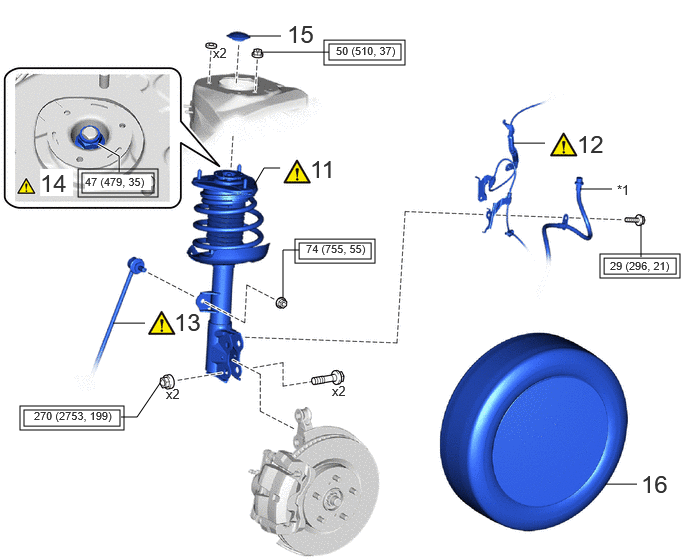
| Procedure | Part Name Code |
|
|
|
|
|---|---|---|---|---|---|
| 11 | FRONT SHOCK ABSORBER WITH COIL SPRING | - | (202307,999999,_53,_112966,_0502991,RM100000002C39Y_01_0001,)
|
- | - |
| 12 | FRONT SPEED SENSOR | 89543 | (202307,999999,_53,_112966,_0502991,RM100000002C39Y_01_0040,)
|
- | - |
| 13 | FRONT STABILIZER LINK ASSEMBLY | 48810 | (202307,999999,_53,_112966,_0502991,RM100000002C39Y_01_0003,)
|
- | - |
| 14 | FRONT SUPPORT TO FRONT SHOCK ABSORBER NUT | 48609E | (202307,999999,_53,_112966,_0502991,RM100000002C39Y_01_0022,)
|
- | - |
| 15 | FRONT SUSPENSION SUPPORT DUST COVER | 48684B | - | - | - |
| 16 | FRONT WHEEL | - | - | - | - |
| *1 | FRONT FLEXIBLE HOSE | - | - |
|
|
Tightening torque for "Major areas involving basic vehicle performance such as moving/turning/stopping" : N*m (kgf*cm, ft.*lbf) | - | - |
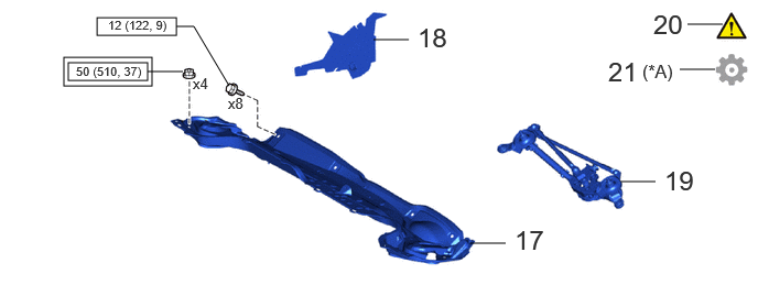
| Procedure | Part Name Code |
|
|
|
|
|---|---|---|---|---|---|
| 17 | OUTER COWL TOP PANEL SUB-ASSEMBLY | 55701J | - | - | - |
| 18 | NO. 1 HEATER AIR DUCT SPLASH SHIELD SEAL | 55737B | - | - | - |
| 19 | WINDSHIELD WIPER MOTOR AND LINK ASSEMBLY | - | - | - | - |
| 20 | INSPECT AND ADJUST FRONT WHEEL ALIGNMENT | - | (202307,999999,_53,_112966,_0502991,RM100000002C39Y_01_0005,)
|
- | - |
| 21 | PERFORM CALIBRATION | - | - | - | (202307,999999,_53,_112966,_0502991,RM100000002C39Y_01_0057,)
|
| *A | w/ Panoramic view monitor system | - | - |
|
|
Tightening torque for "Major areas involving basic vehicle performance such as moving/turning/stopping" : N*m (kgf*cm, ft.*lbf) | 
|
N*m (kgf*cm, ft.*lbf): Specified torque |
CAUTION / NOTICE / HINT
- HINT:
- ·
Use the same procedure for the RH side and LH side.
·The following procedure is for the LH side.
PROCEDURE

 48158C
1.INSTALL FRONT LOWER COIL SPRING INSULATOR
48158C
1.INSTALL FRONT LOWER COIL SPRING INSULATOR
|
|
|

|
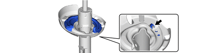
Positioning Pin | - | - |
48331C
2.INSTALL FRONT SPRING BUMPER
|
|
|


|
Install in this direction | - | - |
48132
3.INSTALL FRONT COIL SPRING
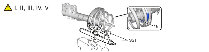
| *a | Depression | - | - |
Secure SST in a vise.
- SST
- 09727-00051
09727-30022 (09727-00010, 09727-00031)
Attach the hooks of each SST arm across the diameter of the coil spring.
- CAUTION:
- ·
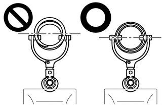
Make sure that the hooks are securely attached to the coil spring.
·If a hook disengages from the coil spring, the coil spring may fly out, resulting in injury.
·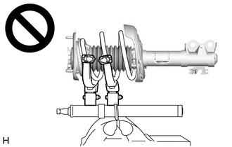
Make sure that the hooks of the upper and lower SST arms are attached to the coil spring so that the distance between the hooks is as large as possible.
·If a hook disengages from the coil spring, the coil spring may fly out, resulting in injury.
·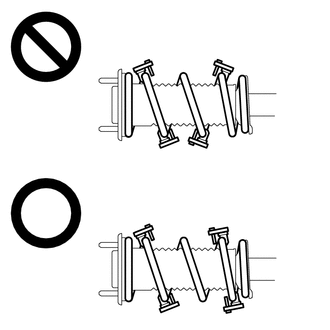
Make sure that the arms of SST are parallel and the number of coils between the arms is the same on each side.
·If a hook disengages from the coil spring, the coil spring may fly out, resulting in injury.
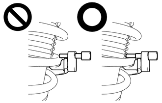
Install the stopper pins to the hooks of SST.
- CAUTION:
-
- ·
Make sure that the stopper pins are installed securely.
·If a hook disengages from the coil spring, the coil spring may fly out, resulting in injury.
Using SST, compress the coil spring.
- CAUTION:
- ·
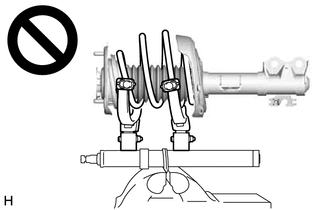
If the coil spring starts to bow out while using SST, stop immediately and reattach SST correctly.
·If a hook disengages from the coil spring, the coil spring may fly out, resulting in injury.
·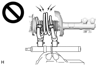
Do not compress the coil spring to the point where the coils touch each other.
·If a hook disengages from the coil spring, the coil spring may fly out, resulting in injury.
·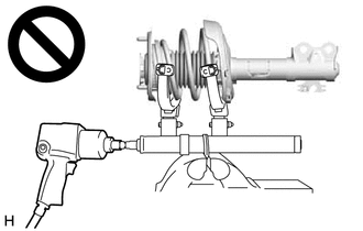
Do not use an impact wrench.
·If an impact wrench is used, the threads of SST may be damaged, or sudden compression of the coil spring may cause a hook to disengage and the coil spring to fly out, resulting in injury.
·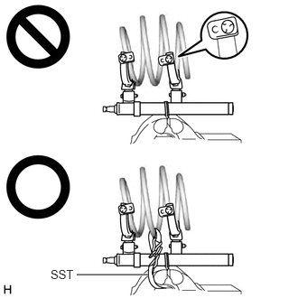 0.885,3.167 1.708,3.167 true 0.583,3.083 0.896,3.24 0.313,0.156 10 false SST
If a stopper pin touches the coil spring while using SST, remove the stopper pin and continue with the procedure.
·If a stopper pin is removed, install a coil spring stopper belt as shown in the illustration.
·If a hook disengages from the coil spring, the coil spring may fly out, resulting in injury.
- SST
- 09727-00110
Align the end of the front coil spring with the flange of the front lower coil spring insulator and install the front coil spring.
- NOTICE:
-
Make sure to fit the end of the front coil spring that has the larger diameter into the depression of the front lower coil spring insulator.
48619A
4.INSTALL STRUT MOUNTING BEARING
|
|
|
|
|
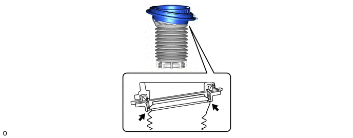
Top End of the Front No. 1 Shock Absorber Dust Cover | - | - |
48157C
5.INSTALL FRONT UPPER COIL SPRING INSULATOR
6.INSTALL STRUT MOUNTING BEARING WITH DUST COVER
48609
7.INSTALL FRONT SUSPENSION SUPPORT SUB-ASSEMBLY
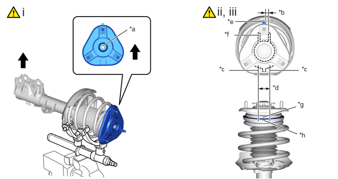
| *a | Slot | *b | 0°+/- 5° |
| *c | Guide Line of Front Suspension Support Sub-assembly | *d | Area in Which Protrusions Must Be Aligned |
| *e | Protrusion of Front Suspension Support Sub-assembly | *f | Front Shock Absorber Lower Bracket |
| *g | Protrusion of Upper Case | *h | Protrusion of Lower Case |
|
|
Outside of the Vehicle | - | - |
Install the front suspension support sub-assembly as shown in the illustration.
- NOTICE:
-
Check that the slot on the piston rod and the slot on the front suspension support sub-assembly are aligned.
Align the protrusion of the front suspension support sub-assembly with the front shock absorber lower bracket as shown in the illustration.
- NOTICE:
-
Make sure to install the front suspension support sub-assembly so that the protrusion of the front suspension support sub-assembly is aligned within +/- 5° of the center of the front shock absorber lower bracket.
Align the protrusions of the upper case and lower case of the strut mounting bearing as shown in the illustration.
- NOTICE:
-
Make sure to install the strut mounting bearing with dust cover so that the protrusion of the upper case of the strut mounting bearing overlaps with the protrusion of the lower case within the guide lines of the front suspension support sub-assembly.
8.INSTALL COLLAR
48609E
9.TEMPORARILY TIGHTEN FRONT SUPPORT TO FRONT SHOCK ABSORBER NUT

Temporarily tighten a new front support to front shock absorber nut.
Remove SST from the front coil spring.
- NOTICE:
-
Do not use an impact wrench. It will damage SST.
48559B
10.CONNECT FRONT NO. 1 SHOCK ABSORBER DUST COVER
|
|
|

| *1 | Front No. 1 Shock Absorber Dust Cover | - | - |
| *a | Claw | - | - |
11.INSTALL FRONT SHOCK ABSORBER WITH COIL SPRING
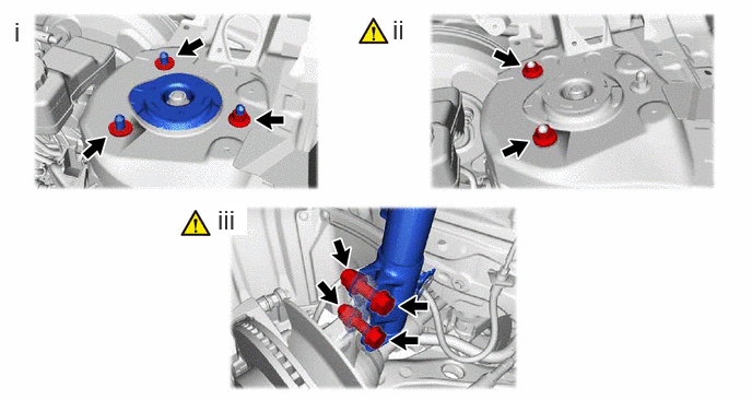
Install the front shock absorber with coil spring (upper side) with the nut and 2 spacers.
- Torque:
- 50 N*m (510 kgf*cm, 37 ft.*lbf)
Temporarily install the 2 nuts to the front shock absorber assembly.
Install the front shock absorber with coil spring (lower side) to the steering knuckle with the 2 bolts and 2 nuts.
- Torque:
- 270 N*m (2753 kgf*cm, 199 ft.*lbf)
- NOTICE:
- ·
When installing the nuts, keep the bolts from rotating.
·Do not apply lubricants to the steering knuckle and shock absorber contact surfaces.
- HINT:
-
The bolts can be installed in either direction, however, make sure that they are both installed in the same direction.
89543
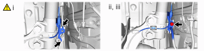
12.INSTALL FRONT SPEED SENSOR
|
|
Hook | - | - |
Set the 2 hooks of front speed sensor to the front shock absorber assembly.
- NOTICE:
-
Do not twist the front speed sensor when installing it.
Install the front speed sensor and front flexible hose to the front shock absorber assembly with the bolt.
- Torque:
- 29 N*m (296 kgf*cm, 21 ft.*lbf)
Engage the clamp.
48810
13.INSTALL FRONT STABILIZER LINK ASSEMBLY

Install the front stabilizer link assembly to the front shock absorber assembly with the nut.
- Torque:
- 74 N*m (755 kgf*cm, 55 ft.*lbf)
If the ball joint turns together with the nut, use a 6 mm hexagon socket wrench to hold the stud bolt.
48609E
14.FULLY TIGHTEN FRONT SUPPORT TO FRONT SHOCK ABSORBER NUT
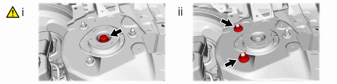
Fully tighten the front support to front shock absorber nut.
- Torque:
- 47 N*m (479 kgf*cm, 35 ft.*lbf)
- NOTICE:
-
Perform this step only when the front shock absorber with coil spring has been disassembled.
Remove the 2 nuts from the front shock absorber assembly.
48684B
15.INSTALL FRONT SUSPENSION SUPPORT DUST COVER
16.INSTALL FRONT WHEEL
55701J
17.INSTALL OUTER COWL TOP PANEL SUB-ASSEMBLY
- Torque:
- Bolt : 12 N*m (122 kgf*cm, 9 ft.*lbf)
- Nut : 50 N*m (510 kgf*cm, 37 ft.*lbf)
55737B
18.INSTALL NO. 1 HEATER AIR DUCT SPLASH SHIELD SEAL
19.INSTALL WINDSHIELD WIPER MOTOR AND LINK ASSEMBLY
20.INSPECT AND ADJUST FRONT WHEEL ALIGNMENT