ALIGNMENT / HANDLING DIAGNOSIS FRONT WHEEL ALIGNMENT ADJUSTMENT
CAUTION / NOTICE / HINT
The necessary procedures (adjustment, calibration, initialization, or registration) that must be performed after completing the front wheel alignment procedure are shown below.
| Replaced Part or Performed Procedure | Necessary Procedure | Effect/Inoperative Function when Necessary Procedure not Performed | Link |
|---|---|---|---|
|
*1: for Gasoline Model *2: for HEV Model |
|||
| Front wheel alignment adjustment | Calibration | ·
DTCs are stored ·
ABS warning light illuminates ·
Slip indicator light illuminates ·
VSC disabled or malfunctions |
( 202307,999999,_54,_112606,_0608078,RM100000002C7D1,)*1 202307,999999,_54,_112606,_0608078,RM100000002C7D1,)*1
( 202307,999999,_54,_112606,_0608077,RM100000002C79U,)*2
|
PROCEDURE

 1.INSPECT TIRES
2.MEASURE VEHICLE HEIGHT
- NOTICE:
- ·
Before inspecting the wheel alignment, first inspect the vehicle height.
·Be sure to perform measurement on a level surface.
·If it is necessary to go under the vehicle for measurement, confirm that the parking brake is applied and the vehicle is secured with chocks.
·Inspect while the vehicle is unloaded.
·The standard value shown here is a value that is used for performing a wheel alignment and does not indicate the height of an actual vehicle.
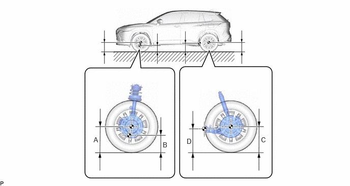
Bounce the vehicle up and down at the corners to stabilize the suspension.
Measure the vehicle height.
A: Ground clearance of front wheel center
B: Ground clearance of front lower No. 1 suspension arm bushing set bolt center
C: Ground clearance of rear wheel center
D: Ground clearance of rear axle beam bushing set bolt center
- Vehicle Height (Unloaded Vehicle):
Engine Front A - B Rear C - D M20#-FKS 105 mm (4.13 in.) 9 mm (0.354 in.) M20#-FXS 110 mm (4.33 in.) 14 mm (0.551 in.)
3.INSPECT CAMBER, CASTER AND STEERING AXIS INCLINATION
- NOTICE:
-
Inspect while the vehicle is unloaded.
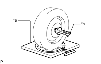
| *a | Turning Radius Gauge |
| *b | Camber-caster-kingpin Gauge |
Install a camber-caster-kingpin gauge and place the front wheels on the center of a turning radius gauge.
Inspect the camber, caster and steering axis inclination.
- Camber (Unloaded Vehicle):
Engine Tire Size Camber Inclination Right-left Difference M20#-FKS 215/60R17 0°09' +/- 0°45' (0.15° +/- 0.75°) 0°45' (0.75°) or less 225/50R18 0°10' +/- 0°45' (0.17° +/- 0.75°) M20#-FXS 215/60R17 0°07' +/- 0°45' (0.12° +/- 0.75°) 225/50R18 0°07' +/- 0°45' (0.12° +/- 0.75°)
- Caster (Unloaded Vehicle):
Engine Tire Size Camber Inclination Right-left Difference M20#-FKS 215/60R17 6°24' +/- 0°45' (6.40° +/- 0.75°) 0°45' (0.75°) or less 225/50R18 6°24' +/- 0°45' (6.40° +/- 0.75°) M20#-FXS 215/60R17 6°28' +/- 0°45' (6.47° +/- 0.75°) 225/50R18 6°27' +/- 0°45' (6.45° +/- 0.75°)
- Steering Axis Inclination (Unloaded Vehicle):
Engine Tire Size Steering Axis Inclination Reference M20#-FKS 215/60R17
225/50R1813°38' (13.63°) M20#-FXS 215/60R17
225/50R1813°45' (13.75°)
4.ADJUST CAMBER
- NOTICE:
-
Inspect toe-in after the camber has been adjusted.
Remove the front wheel.
Click hereGeneral>MAINTENANCE>TIRE AND WHEEL>REMOVAL202201,999999,_V1,_104397,_0503374,RM100000001ZE9H,
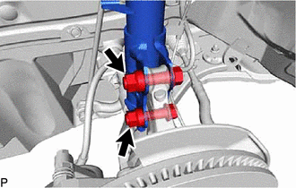
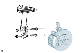
Remove the 2 nuts on the lower side of the front shock absorber assembly.
- NOTICE:
-
Keep the bolts inserted.
Remove the top and bottom bolts one at a time and confirm that the steering knuckle can move freely in the front shock absorber assembly.
- HINT:
- ·
Reinstall each bolt after removing it and confirming steering knuckle movement.
·If the steering knuckle does not move freely in the front shock absorber assembly, clean the contact surfaces of the front shock absorber assembly and the steering knuckle.
Temporarily install the 2 nuts. (Step A)
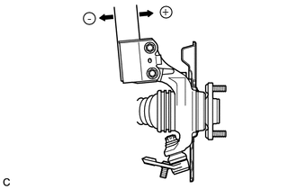
Fully push or pull the front axle hub in the direction of the required adjustment. (Step B)
Tighten the 2 nuts.
- Torque:
- 270 N*m (2753 kgf*cm, 199 ft.*lbf)
- NOTICE:
-
Keep the bolts from rotating when tightening the nuts.
Install the front wheel.
Click hereGeneral>MAINTENANCE>TIRE AND WHEEL>INSTALLATION202201,999999,_V1,_104397,_0503374,RM100000001ZE9I,
Bounce the vehicle up and down at the corners to stabilize the suspension.
Check the camber.
- Camber (Unloaded Vehicle):
Engine Tire Size Camber Inclination Right-left Difference M20#-FKS 215/60R17 0°09' +/- 0°45' (0.15° +/- 0.75°) 0°45' (0.75°) or less 225/50R18 0°10' +/- 0°45' (0.17° +/- 0.75°) M20#-FXS 215/60R17 0°07' +/- 0°45' (0.12° +/- 0.75°) 225/50R18 0°07' +/- 0°45' (0.12° +/- 0.75°)
If the measured value is not within the specification, calculate the required adjustment amount using the formula below.
Camber adjustment amount = center of the specified range - measured value
Check the combination of the installed bolts. Select appropriate bolts from the tables below to adjust the camber to the specified values.
- HINT:
-
Try to adjust the camber to the center of the specified values.
| To move the axle hub toward (+) in step B | To move the axle hub toward (-) in step B |
|---|---|
| Refer to table (1) (To move the axle hub toward the positive side) | Refer to table (2) (To move the axle hub toward the negative side) |
The vehicle body and suspension may be damaged if the camber cannot be correctly adjusted according to the table above.
- NOTICE:
-
Replace the nut with a new one when replacing the bolt.
Table (1) (To move the axle hub toward the positive side)
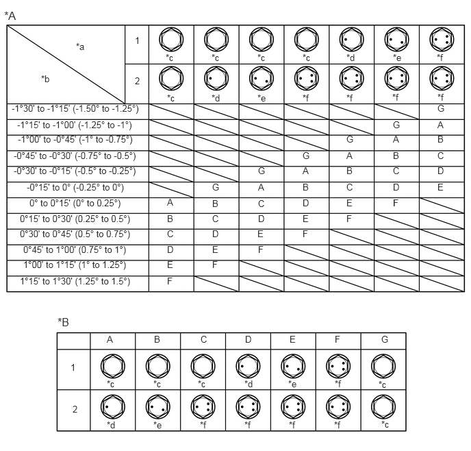
| *A | Table (1) (To move the axle hub toward the positive side) | *B | Selected Bolt Combination |
| *a | Installed Bolt | *b | Adjusting Value |
| *c | Standard Bolt | *d | 90105-17013 |
| *e | 90105-17014 | *f | 90105-17015 |
Table (2) (To move the axle hub toward the negative side)
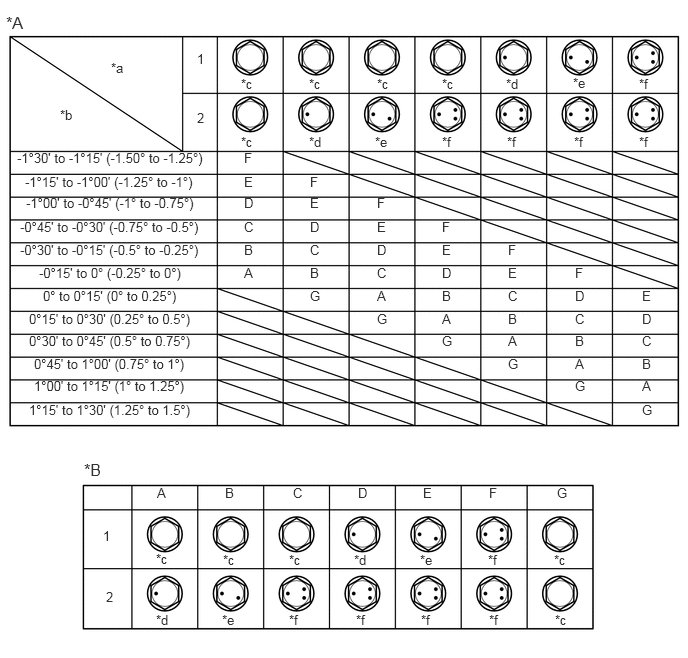
| *A | Table (2) (To move the axle hub toward the negative side) | *B | Selected Bolt Combination |
| *a | Installed Bolt | *b | Adjusting Value |
| *c | Standard Bolt | *d | 90105-17013 |
| *e | 90105-17014 | *f | 90105-17015 |
If the camber was out of adjustment in the previous step, perform the adjust camber steps mentioned above. In step A, replace the existing bolts with the selected bolts.
- HINT:
-
Replace one bolt at a time when replacing both bolts.
5.INSPECT TOE-IN
- NOTICE:
-
Inspect while the vehicle is unloaded.
Bounce the vehicle up and down at the corners to stabilize the suspension.
Release the parking brake and move the shift lever to N.
Push the vehicle straight ahead approximately 5 m (16.4 ft.). (Step C)
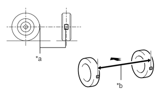
| *a | Tread Center Mark |
| *b | Dimension B |

|
Front of the Vehicle |
Put tread center marks on the rearmost points of the front wheels and measure the distance between the marks (dimension B).
Slowly push the vehicle straight ahead to cause the front wheels to rotate 180°. Use the front tire valve as a reference point.
- HINT:
-
Do not allow the wheels to rotate more than 180°. If the wheels rotate more than 180°, perform the procedure from step C again.
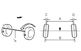
| *a | Dimension A |
|
|
Front of the Vehicle |
Measure the distance between the tread center marks on the front of the wheels (dimension A).
- Toe-in (Unloaded Vehicle):
Engine Tire Size Specified Condition M20#-FKS 215/60R17
225/50R18C+D: 0°07' +/- 0°10' (0.12° +/- 0.17°) B - A: 1.5 +/- 2.0 mm (0.0591 +/- 0.0787 in.) M20#-FXS 215/60R17
225/50R18C+D: 0°08' +/- 0°10' (0.13° +/- 0.17°) B - A: 1.6 +/- 2.0 mm (0.0630 +/- 0.0787 in.)
- HINT:
-
Measure "B - A" only when "C + D" cannot be measured.
If the toe-in is not within the specified range, adjust it at the steering rack ends.
6.ADJUST TOE-IN
Separate the steering rack boot clips from the steering rack boot.
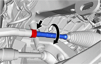
Loosen the tie rod end sub-assembly lock nuts.
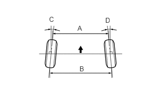
|
|
Front of the Vehicle |
Turn the right and left steering rack ends by an equal amount to adjust the toe-in.
- HINT:
- ·
If the toe-in measurement is more than the specified range, shorten the left and right steering rack ends until the measurement is within the specified range.
·If the toe-in measurement is less than the specified range, extend the left and right steering rack ends until the measurement is within the specified range.
Measure the toe-in.
- Toe-in (Unloaded Vehicle):
Engine Tire Size Specified Condition M20#-FKS 215/60R17
225/50R18C+D: 0°07' +/- 0°10' (0.12° +/- 0.17°) B - A: 1.5 +/- 2.0 mm (0.0591 +/- 0.0787 in.) M20#-FXS 215/60R17
225/50R18C+D: 0°08' +/- 0°10' (0.13° +/- 0.17°) B - A: 1.6 +/- 2.0 mm (0.0630 +/- 0.0787 in.)
- HINT:
-
Perform adjustments so that the value is as close as possible to the median of the specified range.
Tighten the tie rod end sub-assembly lock nuts.
for RH side:
- HINT:
-
Perform the same procedure as for the LH side.
Place the steering rack boots on the seats and install the steering rack boot clips.
for RH side:
- HINT:
-
Perform the same procedure as for the LH side.
7.INSPECT WHEEL ANGLE
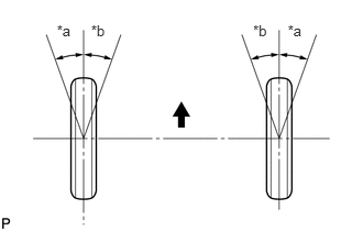
| *a | Inside |
| *b | Outside |
|
|
Front of the Vehicle |
Put tread center marks on the rearmost points of a turning radius gauge.
Turn the steering wheel fully to the left and right and measure the turning angle.
- NOTICE:
-
Inspect while the vehicle is unloaded.
- Wheel Turning Angle (Unloaded Vehicle):
Engine Tire Size Inside Wheel Outside Wheel M20#-FKS 215/60R17 39°40' +/- 2°00' (39.67° +/- 2.00°) 33°58' (33.97°) 225/50R18 39°41' +/- 2°00' (39.68° +/- 2.00°) 33°57' (33.95°) M20#-FXS 215/60R17 39°31' +/- 2°00' (39.52° +/- 2.00°) 33°53' (33.88°) 225/50R18 39°32' +/- 2°00' (39.53° +/- 2.00°) 33°53' (33.88°)
If the right and left inside wheel angles differ from the specified value, check and adjust the right and left steering rack end lengths.
8. ALIGN FRONT WHEELS FACING STRAIGHT AHEAD
9.PERFORM ACCELERATION SENSOR ZERO POINT CALIBRATION AND STORE SYSTEM INFORMATION MEMORIZATION