POWER ASSIST SYSTEMS POWER STEERING ECU INSTALLATION
CAUTION / NOTICE / HINT
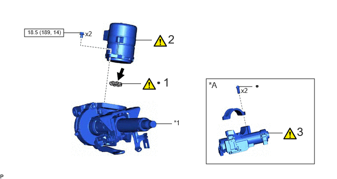
| Procedure | Part Name Code | 
|

|

|
|
|---|---|---|---|---|---|
| 1 | ELECTRIC POWER STEERING MOTOR SHAFT DAMPER | 45254B | ( 202307,999999,_55,_112287,_0500993,RM100000002C2X2_01_0007,) 202307,999999,_55,_112287,_0500993,RM100000002C2X2_01_0007,)
|
- | - |
| 2 | POWER STEERING ECU ASSEMBLY | 89650 | (202307,999999,_55,_112287,_0500993,RM100000002C2X2_01_0008,)
|
- | - |
| 3 | UPPER STEERING COLUMN BRACKET WITH SWITCH ASSEMBLY | 45280A | (202307,999999,_55,_112287,_0500993,RM100000002C2X2_01_0015,)
|
- | - |
| *A | w/o Smart Entry and Start System | - | - |
| *1 | ELECTRIC POWER STEERING COLUMN SUB-ASSEMBLY | - | - |

|
N*m (kgf*cm, ft.*lbf): Specified torque | ● | Non-reusable part |

|
Grease | - | - |
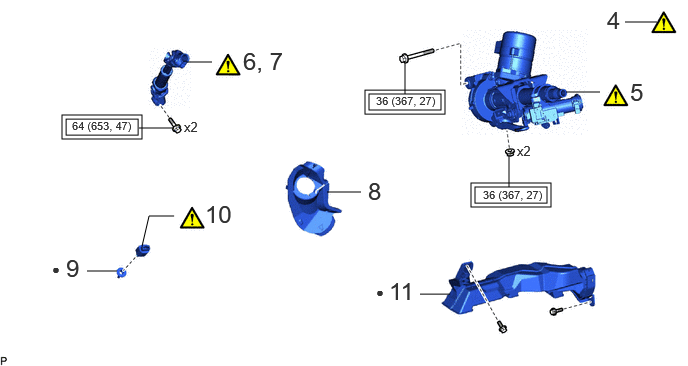
| Procedure | Part Name Code |
|
|
|
|
|---|---|---|---|---|---|
| 4 | ALIGN FRONT WHEELS FACING STRAIGHT AHEAD | - | (202307,999999,_55,_112287,_0500993,RM100000002C2X2_01_0019,)
|
- | - |
| 5 | STEERING COLUMN ASSEMBLY | - | (202307,999999,_55,_112287,_0500993,RM100000002C2X2_01_0018,)
|
- | - |
| 6 | INSTALL NO. 2 STEERING INTERMEDIATE SHAFT ASSEMBLY | 45260 | (202307,999999,_55,_112287,_0500993,RM100000002C2X2_01_0027,)
|
- | - |
| 7 | CONNECT NO. 2 STEERING INTERMEDIATE SHAFT ASSEMBLY | 45260 | (202307,999999,_55,_112287,_0500993,RM100000002C2X2_01_0028,)
|
- | - |
| 8 | COLUMN HOLE COVER SILENCER SHEET | 45259A | - | - | - |
| 9 | STOP LIGHT SWITCH MOUNTING ADJUSTER | 84345 | - | - | - |
| 10 | STOP LIGHT SWITCH ASSEMBLY | 84340 | (202307,999999,_55,_112287,_0500993,RM100000002C2X2_01_0038,)
|
- | - |
| 11 | NO. 1 AIR DUCT | 87211 | - | - | - |

|
Tightening torque for "Major areas involving basic vehicle performance such as moving/turning/stopping" : N*m (kgf*cm, ft.*lbf) | ● | Non-reusable part |
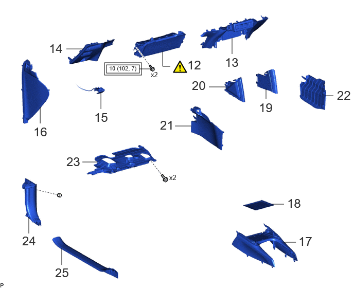
| Procedure | Part Name Code |
|
|
|
|
|---|---|---|---|---|---|
| 12 | LOWER NO. 1 INSTRUMENT PANEL AIRBAG ASSEMBLY | 73900 | (202307,999999,_55,_112287,_0500993,RM100000002C2X2_01_0025,)
|
- | - |
| 13 | LOWER CENTER INSTRUMENT PANEL FINISH PANEL | 55434F | - | - | - |
| 14 | LOWER INSTRUMENT PANEL FINISH PANEL | 55432B | - | - | - |
| 15 | HOOD LOCK CONTROL LEVER SUB-ASSEMBLY | 53601 | - | - | - |
| 16 | NO. 1 INSTRUMENT SIDE PANEL | 55317E | - | - | - |
| 17 | FRONT CONSOLE UPPER PANEL GARNISH | 58831A | - | - | - |
| 18 | NO. 2 BOX BOTTOM MAT | 58917 | - | - | - |
| 19 | NO. 1 CONSOLE UPPER PANEL GARNISH | 58833B | - | - | - |
| 20 | NO. 2 CONSOLE UPPER PANEL GARNISH | 58834B | - | - | - |
| 21 | NO. 1 FRONT CONSOLE BOX INSERT | 58816D | - | - | - |
| 22 | NO. 2 FRONT CONSOLE BOX INSERT | 58817A | - | - | - |
| 23 | NO. 1 INSTRUMENT PANEL UNDER COVER SUB-ASSEMBLY | 55606 | - | - | - |
| 24 | COWL SIDE TRIM SUB-ASSEMBLY LH | 62112A | - | - | - |
| 25 | FRONT DOOR SCUFF PLATE LH | 57914B | - | - | - |
|
|
Tightening torque for "Major areas involving basic vehicle performance such as moving/turning/stopping": N*m (kgf*cm, ft.*lbf) | - | - |
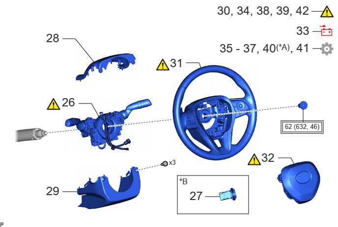
| Procedure | Part Name Code |
|
|
|
|
|---|---|---|---|---|---|
| 26 | TURN SIGNAL SWITCH ASSEMBLY WITH SPIRAL CABLE SUB-ASSEMBLY | - | (202307,999999,_55,_112287,_0500993,RM100000002C2X2_01_0024,)
|
- | - |
| 27 | TRANSPONDER KEY COIL | 89782 | - | - | - |
| 28 | UPPER STEERING COLUMN COVER | 45286B | - | - | - |
| 29 | LOWER STEERING COLUMN COVER | 45287 | - | - | - |
| 30 | ADJUST SPIRAL CABLE WITH SENSOR SUB-ASSEMBLY | - | (202307,999999,_55,_112287,_0500993,RM100000002C2X2_01_0040,)
|
- | - |
| 31 | STEERING WHEEL ASSEMBLY | 45100 | (202307,999999,_55,_112287,_0500993,RM100000002C2X2_01_0020,)
|
- | - |
| 32 | HORN BUTTON ASSEMBLY | 45130 | (202307,999999,_55,_112287,_0500993,RM100000002C2X2_01_0034,)
|
- | - |
| 33 | CONNECT CABLE TO NEGATIVE AUXILIARY BATTERY TERMINAL | - | - | - | - |
| 34 | INSPECT HORN BUTTON ASSEMBLY | 45130 | (202307,999999,_55,_112287,_0500993,RM100000002C2X2_01_0032,)
|
- | - |
| 35 | UPDATE ECU SECURITY KEY | - | - | - | (202307,999999,_55,_112287,_0500993,RM100000002C2X2_01_0039,)
|
| 36 | PERFORM POWER STEERING ECU INITIAL SETTING (TORQUE SENSOR ZERO POINT CALIBRATION AND ASSIST MAP WRITING) | - | - | - | (202307,999999,_55,_112287,_0500993,RM100000002C2X2_01_0013,)
|
| 37 | PERFORM END POSITION INITIAL SETTING | - | - | - | (202307,999999,_55,_112287,_0500993,RM100000002C2X2_01_0016,)
|
| 38 | PERFORM DIAGNOSTIC SYSTEM CHECK | - | (202307,999999,_55,_112287,_0500993,RM100000002C2X2_01_0031,)
|
- | - |
| 39 | INSPECT SRS WARNING LIGHT | - | (202307,999999,_55,_112287,_0500993,RM100000002C2X2_01_0030,)
|
- | - |
| 40 | PERFORM CALIBRATION | - | - | - | (202307,999999,_55,_112287,_0500993,RM100000002C2X2_01_0017,)
|
| 41 | INITIALIZATION AFTER RECONNECTING AUXILIARY BATTERY TERMINAL | - | - | - | (202307,999999,_55,_112287,_0500993,RM100000002C2X2_01_0035,)
|
| 42 | CHECK STEERING WHEEL CENTER POINT | - | (202307,999999,_55,_112287,_0500993,RM100000002C2X2_01_0036,)
|
- | - |
| *A | w/ Panoramic View Monitor System | *B | w/o Smart Entry and Start System |
|
|
Tightening torque for "Major areas involving basic vehicle performance such as moving/turning/stopping" : N*m (kgf*cm, ft.*lbf) | - | - |
CAUTION / NOTICE / HINT
- NOTICE:
- ·
After replacing the power steering ECU assembly, make sure to perform update ECU security key.
·After performing the update ECU security key procedure, make sure to perform the initialization procedure for when the cable has been disconnected and reconnected to the negative (-) auxiliary battery terminal.
PROCEDURE

 45254B
1.INSTALL ELECTRIC POWER STEERING MOTOR SHAFT DAMPER
45254B
1.INSTALL ELECTRIC POWER STEERING MOTOR SHAFT DAMPER
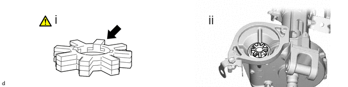
|
|
Grease | - | - |
Apply grease to a new electric power steering motor shaft damper.
- NOTICE:
-
First wipe off the existing grease from the serrated part, and then apply the dedicated grease supplied with a new power steering ECU assembly or electric power steering column sub-assembly.
Install the electric power steering motor shaft damper.
89650
2.INSTALL POWER STEERING ECU ASSEMBLY
|
|
|
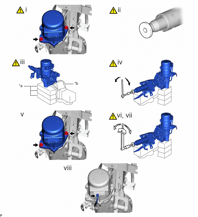
| *a | Wooden Block | *b | Cloth |

|
Rotate | 
|
Turn |
Temporarily install the power steering ECU assembly with the 2 bolts.
- NOTICE:
-
When temporarily installing the 2 bolts to the power steering ECU assembly, do not tighten them all the way down.
Using a 10 mm hexagon socket wrench, install the steering wheel assembly set bolt to the steering main shaft.
- NOTICE:
-
Do not apply excessive torque to the steering wheel assembly set bolt by using a tool such as an impact wrench.
- HINT:
-
The steering wheel assembly set bolt is used for turning the steering main shaft during inspection of the steering main shaft rotating torque. Remove the steering wheel assembly set bolt after performing this inspection.
Secure the steering column assembly in a vise using aluminum plates, cloths and wooden blocks.
- NOTICE:
- ·
Do not overtighten the vise, as the steering column assembly may become deformed.
·Secure the power steering ECU assembly so that it is upright.
·Support the steering column assembly with wooden blocks or similar items to ensure that it does not fall.
Rotate the steering main shaft 180 degrees counterclockwise and then 180 degrees clockwise at a speed of 60 rpm, and repeat 2 to 3 times to center the axis of the power steering ECU assembly. [*1]
Tighten the 2 bolts. [*2]
- Torque:
- 18.5 N*m (189 kgf*cm, 14 ft.*lbf)
Using a torque wrench, measure the turning torque of the steering main shaft.
- Preload:
1.1 to 2.3 N*m (12 to 23 kgf*cm, 10 to 20 in.*lbf)
- NOTICE:
-
Ensure that there is no abnormal resistance during rotation.
If the turning torque is not as specified, loosen the 2 bolts and repeat steps [*1] and [*2] to recenter the axis of the power steering ECU assembly.
Connect the connector.
45280A
3.INSTALL UPPER STEERING COLUMN BRACKET WITH SWITCH ASSEMBLY (w/o Smart Entry and Start System)
4.ALIGN FRONT WHEELS FACING STRAIGHT AHEAD
5.INSTALL STEERING COLUMN ASSEMBLY
45260
6.INSTALL NO. 2 STEERING INTERMEDIATE SHAFT ASSEMBLY
45260
7.CONNECT NO. 2 STEERING INTERMEDIATE SHAFT ASSEMBLY
45259A
8.INSTALL COLUMN HOLE COVER SILENCER SHEET
84345
9.INSTALL STOP LIGHT SWITCH MOUNTING ADJUSTER
84340
10.INSTALL STOP LIGHT SWITCH ASSEMBLY
87211
11.INSTALL NO. 1 AIR DUCT
73900
12.INSTALL LOWER NO. 1 INSTRUMENT PANEL AIRBAG ASSEMBLY
55434F
13.INSTALL LOWER CENTER INSTRUMENT PANEL FINISH PANEL
55432B
14.INSTALL LOWER INSTRUMENT PANEL FINISH PANEL
53601
15.CONNECT HOOD LOCK CONTROL LEVER SUB-ASSEMBLY
55317E
16.INSTALL NO. 1 INSTRUMENT SIDE PANEL
58831A
17.INSTALL FRONT CONSOLE UPPER PANEL GARNISH
58917
18.INSTALL NO. 2 BOX BOTTOM MAT
58833B
19.INSTALL NO. 1 CONSOLE UPPER PANEL GARNISH
58834B
20.INSTALL NO. 2 CONSOLE UPPER PANEL GARNISH
58816D
21.INSTALL NO. 1 FRONT CONSOLE BOX INSERT
58817A
22.INSTALL NO. 2 FRONT CONSOLE BOX INSERT
55606
23.INSTALL NO. 1 INSTRUMENT PANEL UNDER COVER SUB-ASSEMBLY
62112A
24.INSTALL COWL SIDE TRIM SUB-ASSEMBLY LH
67914B
25.INSTALL FRONT DOOR SCUFF PLATE LH
26.INSTALL TURN SIGNAL SWITCH ASSEMBLY WITH SPIRAL CABLE SUB-ASSEMBLY
89782
27.INSTALL TRANSPONDER KEY COIL (w/o Smart Entry and Start System)
45286B
28.INSTALL UPPER STEERING COLUMN COVER
45287
29.INSTALL LOWER STEERING COLUMN COVER
30.ADJUST SPIRAL CABLE WITH SENSOR SUB-ASSEMBLY
45100
31.INSTALL STEERING WHEEL ASSEMBLY
45130
32.INSTALL HORN BUTTON ASSEMBLY
33.CONNECT CABLE TO NEGATIVE AUXILIARY BATTERY TERMINAL
45130
34.INSPECT HORN BUTTON ASSEMBLY
35. UPDATE ECU SECURITY KEY
36. PERFORM POWER STEERING ECU INITIAL SETTING (TORQUE SENSOR ZERO POINT CALIBRATION AND ASSIST MAP WRITING)
37.PERFORM END POSITION INITIAL SETTING
38. PERFORM DIAGNOSTIC SYSTEM CHECK
39.INSPECT SRS WARNING LIGHT
40.PERFORM CALIBRATION (w/ Panoramic View Monitor System)
41. INITIALIZATION AFTER RECONNECTING AUXILIARY BATTERY TERMINAL
- HINT:
-
When disconnecting and reconnecting the auxiliary battery, there is an automatic learning function that completes learning when the respective system is used.
42.CHECK STEERING WHEEL CENTER POINT