STEERING COLUMN STEERING SYSTEM ADJUSTMENT
PROCEDURE

 1. STEERING OFF CENTER ADJUSTMENT
- HINT:
-
This is the adjustment procedure for when the steering is off-center.
Check if the steering wheel assembly is off-center.
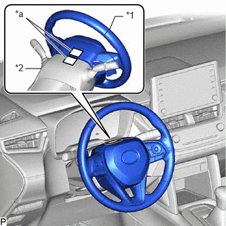
| *1 | Steering Wheel Assembly |
| *2 | Upper Steering Column Cover |
| *a | Masking Tape |
Apply masking tape to the top center of the steering wheel assembly and upper steering column cover.
Drive the vehicle in a straight line for 100 m (328 ft.) at a constant speed of 56 km/h (35 mph) and hold the steering wheel assembly to maintain the course.
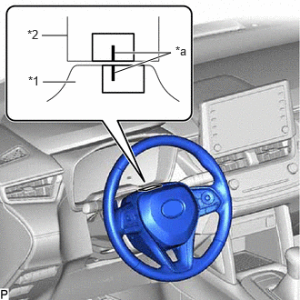
| *1 | Steering Wheel Assembly |
| *2 | Upper Steering Column Cover |
| *a | Marked Line |
Draw a line on the masking tape as shown in the illustration.
Turn the steering wheel assembly to the center position.
- HINT:
-
Look at the upper surface of the steering wheel assembly, steering spoke and SRS airbag line to find the center position.
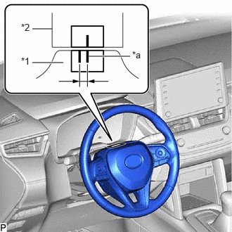
| *1 | Steering Wheel Assembly |
| *2 | Upper Steering Column Cover |
| *a | Marked Line |
Draw a new line on the masking tape on the steering wheel assembly as shown in the illustration.
Measure the distance between the 2 lines on the masking tape on the steering wheel assembly.
Convert the measured distance to a steering angle value.
- HINT:
- ·
Measured distance 1 mm (0.0394 in.) = Steering angle of approximately 1°.
- ·
Make a note of the steering angle.
Adjust the steering angle.
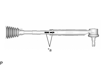
| *a | Matchmark |
Place matchmarks on the RH and LH tie rod end sub-assemblies and steering rack end sub-assemblies respectively where they can be easily seen.
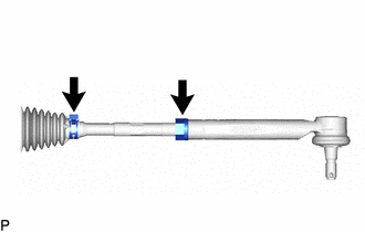
Remove the RH and LH steering rack boot clips from the steering rack boots.
Loosen the RH and LH lock nuts.
Turn the RH and LH steering rack end sub-assemblies by the same amount (but in different directions) according to the steering angle value.
Tighten the RH and LH lock nuts to the specified torque.
Install the RH and LH steering rack boot clips.
Perform rotation angle sensor output calibration.