SEAT POWER SEAT SWITCH REMOVAL
CAUTION / NOTICE / HINT
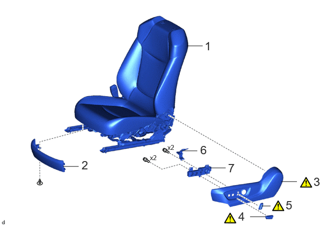
| Procedure | Part Name Code | 
|

|

|
|
|---|---|---|---|---|---|
| 1 | FRONT SEAT ASSEMBLY | - | - | - | - |
| 2 | FRONT SEAT FRONT CUSHION SHIELD | 71868N | - | - | - |
| 3 | FRONT SEAT CUSHION SHIELD | 71812D | ( 202307,999999,_58,_114203,_0509294,RM100000002BZY3_06_0004,) 202307,999999,_58,_114203,_0509294,RM100000002BZY3_06_0004,)
|
- | - |
| 4 | SLIDE AND VERTICAL POWER SEAT SWITCH KNOB | 84921R | (202307,999999,_58,_114203,_0509294,RM100000002BZY3_06_0012,)
|
- | - |
| 5 | RECLINING POWER SEAT SWITCH KNOB | 84921Q | (202307,999999,_58,_114203,_0509294,RM100000002BZY3_06_0011,)
|
- | - |
| 6 | SEAT ADJUSTER SHIELD CLAMP BRACKET | 72714 | - | - | - |
| 7 | FRONT POWER SEAT SWITCH | 84922C | - | - | - |
CAUTION / NOTICE / HINT
The necessary procedures (adjustment, calibration, initialization or registration) that must be performed after parts are removed and installed, or replaced during front power seat switch assembly removal/installation are shown below.
- CAUTION:
-
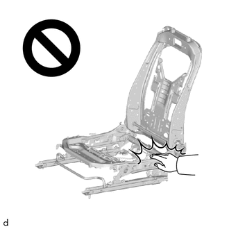
-
Wear protective gloves. Sharp areas on the parts may injure your hands.
- NOTICE:
-
If a front seat airbag assembly has been deployed, replace the front seat airbag assembly, front seatback frame sub-assembly, separate type front seatback pad, separate type front seatback cover and front seatback pad with cover with the necessary parts in accordance with the extent of the collision damage.
- HINT:
- ·
When the cable is disconected / reconnected to the auxiliary battery terminal, systems temporarily stop operating. However, each system has a function that completes learning the first time the system is used.
-Learning completes when vehicle is driven
Effect/Inoperative Function When Necessary Procedures are not Performed Necessary Procedures Link *1: for Gasoline Model
Front camera system Drive the vehicle straight ahead at 15 km/h (10mph) or more for 1 second or more. ( 202307,999999,_95,_112293,_0586709,RM100000002BSVY,)
Stop and start system*1 Drive the vehicle until stop and start control is permitted (approximately 5 to 60 minutes). ( 202307,999999,_51,_115233,_0510781,RM100000002CS0B,)
-Learning completes when vehicle is operated normally
Effect/Inoperative Function When Necessary Procedures are not Performed Necessary Procedures Link Power door lock control system
·Back door opener
Perform door unlock operation with door control switch or electrical key transmitter sub-assembly switch. ( 202201,999999,_58,_115226,_0510939,RM1000000020BSY,)
Power back door system Fully close the back door by hand.
- HINT:
-
Initialization is not necessary if the above procedures are performed while the back door is closed.
( 202201,999999,_59,_113746,_0504731,RM100000001ZJKP,)
Air conditioning system After the ignition switch is turned to ON, the servo motor standard position is recognized. -
·Use the same procedure for the driver side and front passenger side.
·The procedure listed below is for the driver side.
PROCEDURE

 1.REMOVE FRONT SEAT ASSEMBLY
71868N
2.REMOVE FRONT SEAT FRONT CUSHION SHIELD
71812D
3.REMOVE FRONT SEAT CUSHION SHIELD
84921R
4.REMOVE SLIDE AND VERTICAL POWER SEAT SWITCH KNOB
84921Q
5.REMOVE RECLINING POWER SEAT SWITCH KNOB
72714
6.REMOVE SEAT ADJUSTER SHIELD CLAMP BRACKET
84922C
7.REMOVE FRONT POWER SEAT SWITCH
