M20F-FXS, M20G-FXS ENGINE CONTROL SFI SYSTEM Rough Idling
DESCRIPTION
| Problem Symptom | Suspected Area | Trouble Area | |
|---|---|---|---|
·
Engine speed fluctuation due to abnormal combustion ·
Idle speed too low or high Strong engine vibration due to above symptoms |
·
Ignition malfunction ·
Deviation in air fuel ratio (Excessive or insufficient intake air volume or fuel supply) ·
Insufficient compression ·
Changes in load from another system |
·
Spark plug ·
Ignition coil assembly |
Ignition system |
·
Port fuel injector assembly ·
Direct fuel injector assembly ·
Injector driver (ECM) ·
Fuel pump (for low pressure) ·
Fuel pump assembly (for high pressure) ·
Fuel pump control circuit ·
Fuel line ·
Purge VSV system ·
Fuel quality (existence of foreign matter, degradation) |
Fuel system | ||
·
EGR system ·
Mass air flow meter ·
Intake system (Air leaks or deposit accumulation) ·
Throttle body with motor assembly ·
Air fuel ratio sensor (sensor 1) ·
Air fuel ratio sensor (sensor 2) ·
Cam timing control motor with EDU assembly ·
Cam timing oil control solenoid assembly ·
Variable Valve Timing system (VVT-iE, VVT-i system) |
Intake and exhaust systems | ||
·
ECM ·
Wire harness or connector ·
Knock sensor ·
Engine coolant temperature sensor |
Other control systems | ||
·
Water inlet with thermostat sub-assembly ·
Engine assembly ·
Engine mount |
Engine | ||
- HINT:
- ·
If any DTCs are output, perform troubleshooting for the DTCs first.
·Try to reproduce the conditions present when the malfunction occurred.
·Using the GTS, read the Data List to confirm the engine operating conditions. This information can be useful when troubleshooting.
·If the problem symptoms do not recur, attempt to reproduce the symptoms and conditions when the malfunction occurred based on the result of the customer problem analysis. Place the priority on confirming the symptoms.
SYMPTOM AND CAUSE OF SYSTEM MALFUNCTION
- HINT:
-
The following are descriptions of the characteristics of each system malfunction. After understanding the link between the causes and symptoms, perform the inspection of each component. Even if the problem symptom does not recur, signs of the malfunction may be found in the Data List.
Ignition system
| Main cause of malfunction | Performance degradation (wear, existence of foreign matter, etc.) |
| Symptom | Engine speed fluctuation due to abnormal combustion |
| Data List | Misfire Count Cylinder #1 to #4 |
|
|
| Main cause of malfunction | Internal malfunction |
| Problem symptom | Engine speed fluctuation due to abnormal combustion |
| Data List | Misfire Count Cylinder #1 to #4 |
Fuel system
| Main cause of malfunction | Blockage |
| Problem symptom | ·
Engine speed fluctuation due to abnormal combustion ·
Idle speed too low or high |
| Data List | ·
Short FT B1S1 ·
Long FT B1S1 ·
Total FT Bank 1 ·
Fuel System Status Bank 1 ·
Target Air-Fuel Ratio ·
A/F (O2) Lambda Sensor B1S1 ·
A/F Learn Value Idle (Port) Bank 1 ·
A/F Learn Value Low (Port) Bank 1 ·
A/F Learn Value Mid No.1 (Port) Bank 1 ·
A/F Learn Value Mid No.2 (Port) Bank 1 ·
A/F Learn Value High (Port) Bank 1 ·
A/F Learn Value Idle Bank 1 ·
A/F Learn Value Low Bank 1 ·
A/F Learn Value Mid No.1 Bank 1 ·
A/F Learn Value Mid No.2 Bank 1 ·
A/F Learn Value High Bank 1 ·
A/F Learn Value Low (Dual) Bank 1 ·
A/F Learn Value Mid (Dual) No.1 Bank 1 ·
A/F Learn Value Mid (Dual) No.2 Bank 1 ·
A/F Learn Value High (Dual) Bank 1 |
|
|
|
| Main cause of malfunction | ·
Fuel degradation due to age or water contamination ·
Low fuel quality ·
Addition of fuel additive |
| Problem symptom | ·
Engine speed fluctuation due to abnormal combustion ·
Idle speed too low or high ·
Engine is difficult to start |
Intake and exhaust systems
| Main cause of malfunction | EGR valve movement problems or stuck |
| Problem symptom | ·
Engine speed fluctuation due to abnormal combustion ·
Idle speed too low or high ·
Startability malfunction, lack of power or engine stalls |
| Data List | ·
EGR Step Position ·
Target EGR Valve Position No.1 -
Normally, Actual EGR Position = Target EGR Valve Position No. 1 +/-5% (fully closed: 0%, fully open: 100%) -
When the ignition switch is to ON, the EGR valve fully closes. |
| Main cause of malfunction | Performance degradation (existence of foreign matter, etc.) |
| Problem symptom | Lack of power |
| Data List | Mass Air Flow Sensor |
|
|
| Main cause of malfunction | Inappropriate trim volume adjustment due to accumulation of deposits |
| Problem symptom | ·
Engine speed fluctuation due to abnormal combustion ·
Idle speed too low or high |
| Data List | ·
Engine Stall Control F/B Flow ·
ISC Learning Value |
| Main cause of malfunction | Deviation in sensor characteristics |
| Problem symptom | Abnormal combustion due to deviation of actual air fuel ratio from calculated ratio |
| Data List | ·
A/F (O2) Sensor Current B1S1 ·
A/F (O2) Sensor Current B1S2 ·
Fuel System Status Bank 1 |
Engine
| Main cause of malfunction | ·
Compression loss ·
Accumulation of deposits (Combustion chamber, intake valve or intake manifold) |
| Problem symptom | ·
Engine speed fluctuation due to abnormal combustion ·
Idle speed too low or high ·
Hesitation during acceleration or stalling |
|
|
DATA LIST ITEMS RELATED TO ROUGH IDLING
- HINT:
-
Depending on the vehicle model, the applicable Data List items may vary. Data List items other than the ones used in the diagnostic procedure are for reference only.
- ·
Mass Air Flow Sensor
·Engine Stall Control F/B Flow
·Target Fuel Pressure (High)
·Target Fuel Pressure (Low) / Target Fuel Pressure 2
·Fuel Pressure (High)
·Fuel Pressure (Low) / Fuel Pressure 2
·Fuel Pump Control Duty Ratio
·High Pressure Fuel Pump Duty Ratio (D4)
·High Pressure Fuel Pump Discharge Rate
·Target Air-Fuel Ratio
·A/F (O2) Sensor Current B1S1
·A/F (O2) Sensor Current B1S2
·Short FT B1S1
·Long FT B1S1
·Total FT Bank 1
·Fuel System Status Bank 1
·A/F Learn Value Idle (Port) Bank 1
·A/F Learn Value Low (Port) Bank 1
·A/F Learn Value Mid No.1 (Port) Bank 1
·A/F Learn Value Mid No.2 (Port) Bank 1
·A/F Learn Value High (Port) Bank 1
·A/F Learn Value Idle Bank 1
·A/F Learn Value Low Bank 1
·A/F Learn Value Mid No.1 Bank 1
·A/F Learn Value Mid No.2 Bank 1
·A/F Learn Value High Bank 1
·A/F Learn Value Low (Dual) Bank 1
·A/F Learn Value Mid (Dual) No.1 Bank 1
·A/F Learn Value Mid (Dual) No.2 Bank 1
·A/F Learn Value High (Dual) Bank 1
·Target EGR Valve Position No.1
·EGR Step Position
·Misfire Count Cylinder #1 to #4
·ISC Learning Value
PROCEDURE
Interview the customer for details about the conditions when the rough idle occurred.
- HINT:
-
Depending on the conditions when the rough idle occurred, a malfunction in one of the following areas is suspected.
Problem Symptom Suspected Area Engine runs rough, particularly when idling after a coil start. Engine runs less rough when the engine speed is increased Possibly caused by excessive EGR due to insufficient closing of the EGR valve Hesitation or lack of power occurs during acceleration, regardless of whether engine is cold or warm ·For low mileage vehicles (ODO reading of less than approximately 20000 km (12428 miles) or yearly mileage of less than 2000 km (1243 miles)): Fuel quality (degradation, water contamination, etc.)
·For high mileage vehicles (ODO reading of more than approximately 150000 km (93210 miles)): Excessively lean air fuel ratio during acceleration due to deposits in intake system or combustion chamber caught temporarily on intake or exhaust valve or adherence of fuel to the deposits
·Abnormal mass air flow meter output due to existence of foreign matter
·Decrease in fuel injector assembly injection volume due to low quality fuel
Engine stalls or is difficult to start immediately after engine stalled, regardless of whether engine is cold or warm Deposits in intake system or combustion chamber caught temporarily on intake or exhaust valve
- Result:
Proceed to NEXT
NEXT
Perform a road test.
Read the DTCs.
- Powertrain > Engine > Trouble Codes
- 50001 372
- Result:
Result Proceed to DTCs are not output A DTC is output B
A
B
Check if the problem symptoms reported in the customer problem analysis recur.
- HINT:
-
If the problem symptoms do not recur, attempt to reproduce the conditions when the malfunction occurred based on the result of the customer problem analysis.
- Result:
Result Proceed to The problem symptom recurs A The problem symptom does not recur (occurred in the past) B
A
B
Enter the following menus.
- Powertrain > Engine > Data List
-
Tester Display ISC Learning Value - 50003 372 424
According to the display on the GTS, read the Data List.
- Result:
Result Proceed to Less than 15 Nm A Other than above B
A
B
Enter the following menus.
- Powertrain > Engine > Data List
-
Tester Display Short FT B1S1 Long FT B1S1 - 50003 372 207,209
According to the display on the GTS, read the Data List.
- Result:
Data List Result Proceed to Short FT B1S1 + Long FT B1S1 -20% or higher, or less than 20% A Other than above B
- HINT:
- ·
"Total FT Bank 1" is used to detect an abnormal air fuel ratio. As the value of "Total FT Bank 1" is corrected by the ECM before it is displayed in the Data List, the displayed value may not be equal to the sum of the measured "Short FT B1S1" and "Long FT B1S1".
·An abnormally lean or rich tendency can be checked by reading the following Data List items: A/F Learn Value Idle (Port) Bank 1, A/F Learn Value Low (Port) Bank 1, A/F Learn Value Mid (Port) No.1 Bank 1, A/F Learn Value Mid (Port) No.2 Bank 1, A/F Learn Value High (Port) Bank 1, A/F Learn Value Idle Bank 1, A/F Learn Value Low Bank 1, A/F Learn Value Mid No.1 Bank 1, A/F Learn Value Mid No.2 Bank 1, A/F Learn Value High Bank 1, A/F Learn Value Low (Dual) Bank 1, A/F Learn Value Mid (Dual) No.1 Bank 1, A/F Learn Value Mid (Dual) No.2 Bank 1 and A/F Learn Value High (Dual) Bank 1. (For vehicles equipped with a V type engine, check that both banks have the same correction tendency. If the correction of either bank is -20% or less or +20% or more, the air fuel ratio sensor (sensor 1) or air fuel ratio sensor (sensor 2) of that bank may be malfunctioning.)
·The following may cause a lean air fuel ratio (an operating range in which the air fuel ratio learned value correction is +20% or more):
(a)Decrease in fuel injector assembly injection volume
(b)Decrease in mass air flow meter output (due to existence of foreign matter)
(c)Air leaks in intake system after mass air flow meter
(d)Decrease in fuel pressure (at fuel filter, fuel pump, fuel main valve assembly or fuel suction plate sub-assembly)
·On vehicles which the learning value for each operating range can be checked, if the value of "A/F Learn Value High (Port) Bank 1", "A/F Learn Value High Bank 1" or "A/F Learn Value High (Dual) Bank 1" only is corrected to the positive side, a malfunction in the fuel system (clogging of the fuel pump or fuel filter) is suspected.
·On vehicles which the learning value for each operating range can be checked, if the value of "A/F Learn Value Idle (Port) Bank 1", "A/F Learn Value Low (Port) Bank 1", "A/F Learn Value Idle Bank 1", "A/F Learn Value Low Bank 1" or "A/F Learn Value Low (Dual) Bank 1" only is corrected to the positive side, an air leak after the mass air flow meter is suspected.
·If the air fuel ratio becomes lean only when the engine is running under a high load and at a high engine speed, clogging of the fuel filter is suspected.
·The following may cause a rich air fuel ratio (an operating range in which the air fuel ratio learned value correction is -20% or less):
(a)Increase in the fuel injector assembly injection volume
(b)Purge VSV system
A
B
Put the engine in Inspection Mode (Maintenance Mode).
- Powertrain > Hybrid Control > Utility
-
Tester Display Inspection Mode - 50005 397 2103
Start the engine.
- HINT:
-
Reproduce the vehicle conditions when the malfunction occurred (such as after the engine is warmed up or after a cold start).
Enter the following menus.
- Powertrain > Engine > Active Test
-
Active Test Display D-4S (Fuel Cut) -
Data List Display Engine Speed - 50004 372 42017 211
According to the display on the GTS, perform the Active Test and check for a malfunctioning cylinder.
- HINT:
- ·
Perform fuel-cut for each cylinder and check the change in the engine speed.
·If the engine speed of a cylinder does not change while performing the Active Test, it can be determined that the cylinder is malfunctioning.
·If the engine speed of all cylinders change while performing the Active Test, it can be determined that multiple cylinders are malfunctioning.
·A cylinder for which the Data List items "Misfire Count Cylinder #1 to #4" increases may be malfunctioning.
- Result:
Result Proceed to One cylinder is malfunctioning A Multiple or all cylinders are malfunctioning, or the malfunctioning cylinder cannot be determined. B
A
B
- NOTICE:
-
Use a fully-charged HV battery.
- HINT:
-
If the vehicle does not support the Active Test Check the Cylinder Compression, measure the compression pressure. If the compression pressure is normal, go to step 8 (PERFORM ACTIVE TEST USING GTS (D-4S (INJECTION VOLUME))).
Warm up the engine.
Turn the ignition switch off.
Put the engine in Inspection Mode (Maintenance Mode).
- Powertrain > Hybrid Control > Utility
-
Tester Display Inspection Mode - 50005 397 2103
- HINT:
-
Do not start the engine.
Enter the following menus.
- Powertrain > Engine > Active Test
-
Active Test Display Check the Cylinder Compression -
Data List Display Engine Speed Cylinder #1 Engine Speed Cylinder #2 Engine Speed Cylinder #3 Engine Speed Cylinder #4 Average Engine Speed of All Cylinder - 50004 372 42007 134,135,136,137,133
- HINT:
-
To display the entire Data List, press the pull down menu button next to Primary. Then select Compression.
Push the snapshot button to turn the snapshot function on.
- HINT:
-
Using the snapshot function, data can be recorded while performing the Active Test.
While the engine is not running, press the Active button to change Check the Cylinder Compression to "Start".
- HINT:
-
After performing the above procedure, Check the Cylinder Compression will start. Fuel injection for all cylinders is prohibited and each cylinder engine speed measurement enters standby mode.
Crank the engine.
- HINT:
-
Continue to crank the engine until the values change from the default value (51199 rpm).
Monitor the engine speed (Engine Speed Cylinder #1 to #4 and Average Engine Speed of All Cylinder) displayed on the GTS.
- NOTICE:
- ·
If the Check the Cylinder Compression Active Test needs to be performed after it is changed to "Start" and performed once, press the Exit button to return to the Active Test menu screen. Then perform the Check the Cylinder Compression Active Test again.
·As soon as the measurements are obtained, stop the Active Test.
- HINT:
- ·
At first, the GTS display will show each cylinder's engine speed measurement to be extremely high. After the engine has started, each cylinder's engine speed measurement will change to the actual engine speed.
·If the cylinder engine speed values (Engine Speed Cylinder #1 to #4) displayed in the Data List do not change from an extremely high value, return to the Active Test menu screen, change "Check the Cylinder Compression" to "Start" and crank the engine again within 1 second.
Stop the engine and change the Active Test "Check the Cylinder Compression" to "Stop" after the engine stops.
- NOTICE:
- ·
When performing the Active Test, DTC may be stored.
·After performing the Active Test, make sure to check and clear the DTCs.
Push the snapshot button to turn the snapshot function off.
Read the value.
- HINT:
- ·
If the value of Data List item "Engine Speed Cylinder" of a cylinder is higher than other cylinders, the cylinder may be malfunctioning.
·If the value of Data List item "Engine Speed Cylinder" is high for only one cylinder, compression loss is suspected.
- Result:
Result Proceed to There is no variation in "Engine Speed Cylinder"
(All cylinders display approximately the same value for "Engine Speed of Cyl")A There is variation in "Engine Speed Cylinder"
(Only one cylinder displays a value for "Engine Speed of Cyl" that differs considerably)B
A
B
Put the engine in Inspection Mode (Maintenance Mode).
- Powertrain > Hybrid Control > Utility
-
Tester Display Inspection Mode - 50005 397 2103
Start the engine and warm it up until the engine coolant temperature is 75°C (167°F) or higher with the A/C switch and all accessories off.
Idle the engine.
Enter the following menus.
- Powertrain > Engine > Active Test
-
Active Test Display D-4S (Injection Volume) -
Data List Display Coolant Temperature - 50004 372 42012 205
According to the display on the GTS, perform the Active Test and check the vehicle conditions when increasing and decreasing the fuel injection volume.
- HINT:
- ·
Increase and decrease the fuel injection volume of the port injection and direct injection simultaneously and check the vehicle condition.
·Change the fuel injection volume between the minimum and maximum range of correction (e.g. -12.5% to 24.8%).
- Result:
Result Proceed to Malfunction is still present even if the fuel injection volume is changed A Malfunction disappears when the fuel injection volume is changed B
A
B
Check the ignition system.
- HINT:
- ·
Interchange the ignition coil assembly and spark plug of the malfunctioning cylinder with those of a known good cylinder and check if the malfunctioning cylinder returns to normal.
·If the spark plug of the malfunctioning cylinder is abnormally wet with fuel even after the ignition coil assembly and spark plug are replaced, a leaking fuel injector assembly is suspected.
- Result:
Result Proceed to The malfunctioning cylinder does not return to normal A The malfunctioning cylinder returned to normal B
A
B
Check the power source circuit, wire harness and connectors.
- Result:
Proceed to NEXT
NEXT
Replace the fuel injector assembly of the malfunctioning cylinder.
- HINT:
- ·
If the air fuel ratio learned value is corrected to the positive side for all operating ranges due to low fuel injector assembly injection volume, replace the fuel injector assemblies of all cylinders.
·If the symptoms tend to improve by decreasing the fuel injection amount, the engine misfire may be due to blockage of an EGR port leading to EGR becoming excessive to the cylinders with little EGR port blockage.
·Perform "Inspection After Repair" after replacing the fuel injector assembly.
- Result:
Proceed to NEXT
NEXT
Measure the cylinder compression pressure. If the compression pressure of a cylinder is low, inspect the engine assembly and repair or replace parts as necessary.
- Result:
Proceed to NEXT
NEXT
Put the engine in Inspection Mode (Maintenance Mode).
- Powertrain > Hybrid Control > Utility
-
Tester Display Inspection Mode - 50005 397 2103
Start the engine and warm it up until the engine coolant temperature is 75°C (167°F) or higher.
- HINT:
-
The A/C switch and all accessories should be off.
Enter the following menus.
- Powertrain > Engine > Active Test
-
Active Test Display Control the EGR Step Position -
Data List Display Intake Manifold Absolute Pressure Coolant Temperature Engine Independent - 50004 372 25 385,205,428
Confirm that the value of Data List item Engine Independent is "Operate" then check the value of Intake Manifold Absolute Pressure while performing the Active Test.
- NOTICE:
- ·
Make sure that the value of Data List item Engine Independent is "Operate" while performing the Active Test.
·Do not leave the EGR valve open for 10 seconds or more during the Active Test.
·Be sure to return the EGR valve to step 0 when the Active Test is completed.
·Do not open the EGR valve 30 steps or more during the Active Test.
- Result:
Result Proceed to Intake Manifold Absolute Pressure increases by less than 10 kPa (1.45 psi) when the EGR valve is fully closed (0 step) A Intake Manifold Absolute Pressure increases by 10 kPa (1.45 psi) or higher when the EGR valve is fully closed (0 step) B
- HINT:
- ·
If the value of Data List item Engine Independent is "Not Opr" when the engine is idling, charge control is being performed. Perform the Active Test after charge control is complete ("Operate" is displayed).
·While performing the Active Test, if the increase in the value of Intake Manifold Absolute Pressure is small, the EGR valve assembly may be malfunctioning.
·Even if the EGR valve assembly is malfunctioning, rough idling or an increase in the value of Intake Manifold Absolute Pressure may occur while performing the Active Test. However, the amount that the value of Intake Manifold Absolute Pressure increases will be smaller than normal.
A
B
- HINT:
-
Perform "Inspection After Repair" after replacing the EGR valve assembly.
- Result:
Proceed to NEXT
NEXT
Put the engine in Inspection Mode (Maintenance Mode).
- Powertrain > Hybrid Control > Utility
-
Tester Display Inspection Mode - 50005 397 3103
Start the engine and warm it up until the engine coolant temperature is 75°C (167°F) or higher with the A/C switch and all accessories off.
Enter the following menus.
- Powertrain > Engine > Data List
-
Tester Display Engine Speed Mass Air Flow Sensor Coolant Temperature - 50003 372 211,215,205
According to the display on the GTS, read the Data List when the engine is running.
- HINT:
-
During charge control, the engine speed is set at idle. Therefore, the engine speed will not increase when the accelerator pedal is depressed. In this case, read the Data List after charge control has completed.
- Result:
Result Proceed to Other than below A Engine speed 2500 rpm (without load): Less than 6.5 gm/sec B
A
B
Put the engine in Inspection Mode (Maintenance Mode).
- Powertrain > Hybrid Control > Utility
-
Tester Display Inspection Mode - 50005 397 2103
Start the engine and warm it up until the engine coolant temperature reaches 75°C (167°F) or higher.
Idle the engine for 5 minutes or more with the shift lever in P.
Enter the following menus.
- Powertrain > Engine > Active Test
-
Active Test Display D-4S (Injection Volume) -
Data List Display Coolant Temperature A/F (O2) Sensor Current B1S1 A/F (O2) Sensor Current B1S2 - 50004 372 42012 205,230,564
According to the display on the GTS, perform the Active Test and check the vehicle conditions when increasing and decreasing the fuel injection volume.
- NOTICE:
- ·
The air fuel ratio sensor (sensor 1) has an output delay of a few seconds and the air fuel ratio sensor (sensor 2) has a maximum output delay of approximately 20 seconds.
·Read the output value immediately after warming up the air fuel ratio sensor (sensor 1) and air fuel ratio sensor (sensor 2) to avoid an inaccurate reading due to a sensor cooling.
- HINT:
- ·
Increase and decrease the fuel injection volume of the port injection and direct injection simultaneously and check the vehicle condition.
·The Active Test "Control the Injection Volume for A/F Sensor" can be used to lower the fuel injection volume by 12.5% or increase the injection volume by 12.5%.
- Standard:
GTS Display
(Sensor)Injection Volume Value A/F (O2) Sensor Current B1S1
(Air fuel ratio (sensor 1))12.5% Below -0.075 mA -12.5% Higher than 0.037 mA A/F (O2) Sensor Current B1S2
(Air fuel ratio (sensor 2))12.5% Below -0.86 mA -12.5% Higher than 0.33 mA
- Result:
Result Proceed to Output values are abnormal A Malfunction disappears when fuel injection volume is increased B Malfunction is still present when fuel injection volume is increased, even if output values are normal C
A
B
C
Replace the air fuel ratio sensor (sensor 1).
- HINT:
-
Perform "Inspection After Repair" after replacing the air fuel ratio sensor (sensor 1).
Replace the air fuel ratio sensor (sensor 2).
- HINT:
-
Perform "Inspection After Repair" after replacing the air fuel ratio sensor (sensor 2).
- Result:
Proceed to NEXT
NEXT
Clean off any deposits inside of the throttle body with motor assembly.
Push open the throttle valve and wipe off any deposits from the valve and bore using a piece of cloth soaked in non-residue solvent.
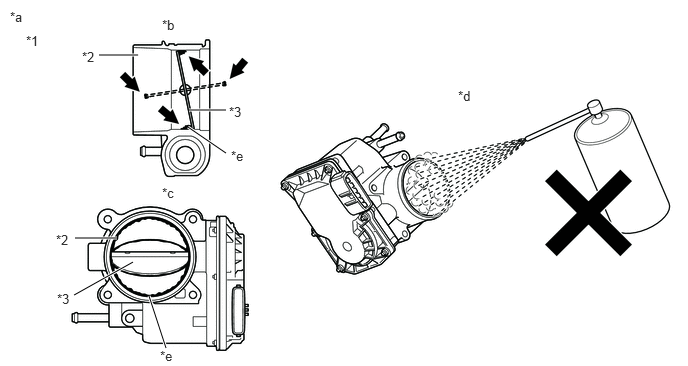
| *1 | Throttle Body with Motor Assembly | *2 | Bore |
| *3 | Throttle Valve | - | - |
| *a | Reference | *b | Throttle Body with Motor Assembly Cross-section Diagram |
| *c | When valve fully opened | *d | Do not directly apply cleaner |
| *e | Deposits | - | - |
- NOTICE:
- ·
Make sure that the cloth or your fingers do not get caught in the valve.
·Make sure that foreign matter does not enter the throttle valve.
·Do not directly apply non-residue solvent to the throttle body with motor assembly or wash the throttle body with motor assembly. Non-residue solvent may leak into the motor from the shaft and cause problems such as rust or valve movement problems.
·If there is coating material on the edge of the throttle valve, be careful not to remove it.
- HINT:
-
The illustration is for reference only, actual parts may differ.
- Result:
Proceed to NEXT
NEXT
Perform "Inspection After Repair" after cleaning the throttle body with motor assembly.
Put the engine in Inspection Mode (Maintenance Mode).
- Powertrain > Hybrid Control > Utility
-
Tester Display Inspection Mode - 50005 397 2103
Start the engine and warm it up until the engine coolant temperature is 75°C (167°F) or higher.
Allow the engine to idle for 3 minutes or more and confirm that the engine speed is within the specified range.
- HINT:
-
If the engine is operated without performing learning value reset and idle learning after cleaning the deposits from the throttle body with motor assembly, the idle speed may increase.
- Result:
Proceed to NEXT
NEXT
Replace the fuel injector assemblies of all cylinders.
- HINT:
-
Perform "Inspection After Repair" after replacing the fuel injector assembly.
- Result:
Proceed to NEXT
NEXT
Inspect other related components.
- HINT:
-
If the malfunctioning part could not be determined by performing the preceding inspections, one of the following malfunctions is suspected.
- ·
Engine mount deterioration
·Deposits in the intake manifold or on an intake valve
·EGR distribution is poor due to EGR port blockage
·Delay in fuel supply due to adherence of the fuel to the deposits
- Result:
Proceed to NEXT
NEXT
Check for air leaks or blockage in the intake system components. If a connection problem or foreign matter is found, repair the connection or remove the foreign matter.
- HINT:
- ·
If there is foreign matter in the intake system components, remove it before proceeding to the next step.
·If there is no foreign matter in the intake system components, check for foreign matter in the mass air flow meter. If there is foreign matter in the mass air flow meter, remove it.
- Result:
Proceed to NEXT
NEXT
Repair or replace the malfunctioning part.
Perform "Inspection After Repair" after repairing or replacing the malfunctioning part.
- Result:
Proceed to NEXT
NEXT
Check that the idle has returned to normal.
- Result:
Proceed to NEXT
NEXT