BRAKE SYSTEM (OTHER) BRAKE PEDAL(for HEV Model) INSTALLATION
CAUTION / NOTICE / HINT
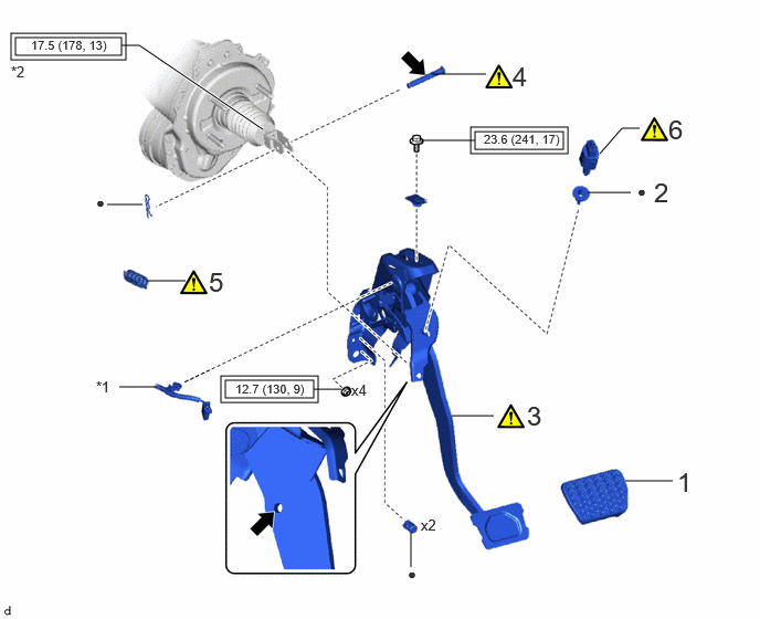
| Procedure | Part Name Code | 
|

|

|
|
|---|---|---|---|---|---|
| 1 | BRAKE PEDAL PAD | 47121 | - | - | - |
| 2 | STOP LIGHT SWITCH MOUNTING ADJUSTER | 84345 | - | - | - |
| 3 | BRAKE PEDAL SUPPORT ASSEMBLY | 47110 | ( 202307,999999,_54,_113942,_0604479,RM100000002BUGV_01_0001,) 202307,999999,_54,_113942,_0604479,RM100000002BUGV_01_0001,)
|
- | - |
| 4 | PUSH ROD PIN | 47264A | (202307,999999,_54,_113942,_0604479,RM100000002BUGV_01_0004,)
|
- | - |
| 5 | BRAKE PEDAL RETURN SPRING | 47101A | (202307,999999,_54,_113942,_0604479,RM100000002BUGV_01_0005,)
|
- | - |
| 6 | STOP LIGHT SWITCH ASSEMBLY | 84340 | (202307,999999,_54,_113942,_0604479,RM100000002BUGV_01_0019,)
|
- | - |
| *1 | WIRE HARNESS | *2 | LOCK NUT |

|
Tightening torque for "Major areas involving basic vehicle performance such as moving/turning/stopping": N*m (kgf*cm, ft.*lbf) | ● | Non-reusable part |

|
Lithium soap base glycol grease | - | - |
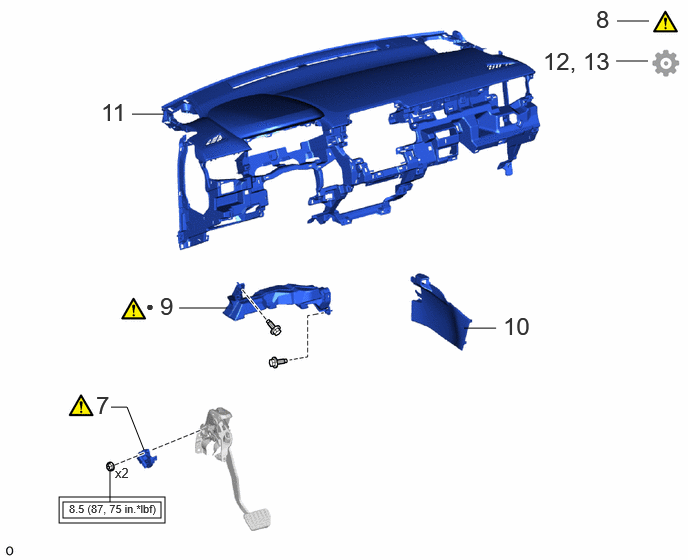
| Procedure | Part Name Code |
|
|
|
|
|---|---|---|---|---|---|
| 7 | BRAKE PEDAL STROKE SENSOR ASSEMBLY | 89510D | (202307,999999,_54,_113942,_0604479,RM100000002BUGV_01_0023,)
|
- | - |
| 8 | INSPECT AND ADJUST BRAKE PEDAL | - | (202307,999999,_54,_113942,_0604479,RM100000002BUGV_01_0013,)
|
- | - |
| 9 | NO. 1 AIR DUCT | 87211 | (202307,999999,_54,_113942,_0604479,RM100000002BUGV_01_0032,)
|
- | - |
| 10 | FRONT NO. 1 CONSOLE BOX INSERT | 58816D | - | - | - |
| 11 | INSTRUMENT PANEL SAFETY PAD ASSEMBLY | 55400 | - | - | - |
| 12 | PERFORM INITIALIZATION AND CALIBRATION | - | - | - | (202307,999999,_54,_113942,_0604479,RM100000002BUGV_01_0037,)
|
| 13 | CHECK AND CLEAR DTC | - | - | - | (202307,999999,_54,_113942,_0604479,RM100000002BUGV_01_0036,)
|
|
|
Tightening torque for "Major areas involving basic vehicle performance such as moving/turning/stopping": N*m (kgf*cm, ft.*lbf) | ● | Non-reusable part |
PROCEDURE

 47121
1.INSTALL BRAKE PEDAL PAD
47121
1.INSTALL BRAKE PEDAL PAD
84345
2.INSTALL STOP LIGHT SWITCH MOUNTING ADJUSTER
47110
3.INSTALL BRAKE PEDAL SUPPORT ASSEMBLY
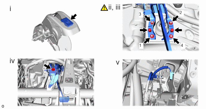
Install the nut to the brake pedal support assembly.
Temporarily install the brake pedal support assembly with 2 new clips.
Install the 4 nuts.
- Torque:
- 12.7 N*m (130 kgf*cm, 9 ft.*lbf)
- NOTICE:
-
Tighten the nuts in the order shown in the illustration.
Install the brake pedal support assembly to the instrument panel reinforcement assembly with the bolt.
- Torque:
- 23.6 N*m (241 kgf*cm, 17 ft.*lbf)
Engage the clamp to install the wire harness to the brake pedal support assembly.
47264A
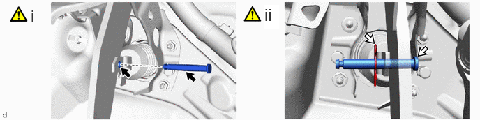
4.INSTALL PUSH ROD PIN
|
|
Lithium soap base glycol grease | - | - |
Apply lithium soap base glycol grease to the push rod pin and installation hole of the brake pedal support assembly.
Connect the brake master cylinder push rod clevis to the brake pedal support assembly with the push rod pin, and install a new clip as shown in the illustration.
- NOTICE:
-
Be sure to install the push rod pin in the correct direction.
47101A
5.INSTALL BRAKE PEDAL RETURN SPRING
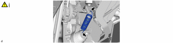
Install the brake pedal return spring to the brake pedal support assembly and push rod pin as shown in the illustration.
84340
6.INSTALL STOP LIGHT SWITCH ASSEMBLY
89510D
7.INSTALL BRAKE PEDAL STROKE SENSOR ASSEMBLY
8.INSPECT AND ADJUST BRAKE PEDAL
87211
9.INSTALL NO. 1 AIR DUCT
58816D
10.INSTALL FRONT NO. 1 CONSOLE BOX INSERT
55400
11.INSTALL INSTRUMENT PANEL SAFETY PAD ASSEMBLY
12.PERFORM INITIALIZATION AND CALIBRATION
After Parts Removed/Installed/Replaced:
After Reconnecting Auxiliary Battery Terminal:
- HINT:
-
When disconnecting and reconnecting the auxiliary battery, there is an automatic learning function that completes learning when the respective system is used.