BRAKE CONTROL / DYNAMIC CONTROL SYSTEMS STEERING ANGLE SENSOR INSTALLATION
CAUTION / NOTICE / HINT
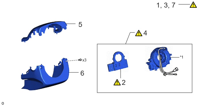
| Procedure | Part Name Code | 
|

|

|
|
|---|---|---|---|---|---|
| 1 | INSPECT SPIRAL CABLE SUB-ASSEMBLY | 84306 | ( 202307,999999,_54,_112606,_0503315,RM100000002BUEZ_01_0062,) 202307,999999,_54,_112606,_0503315,RM100000002BUEZ_01_0062,)
|
- | - |
| 2 | STEERING SENSOR | 89245B | (202307,999999,_54,_112606,_0503315,RM100000002BUEZ_01_0061,)
|
- | - |
| 3 | PLACE FRONT WHEELS FACING STRAIGHT AHEAD | - | (202307,999999,_54,_112606,_0503315,RM100000002BUEZ_01_0066,)
|
- | - |
| 4 | SPIRAL CABLE WITH SENSOR SUB-ASSEMBLY | - | (202307,999999,_54,_112606,_0503315,RM100000002BUEZ_01_0060,)
|
- | - |
| 5 | UPPER STEERING COLUMN COVER | 45286B | - | - | - |
| 6 | LOWER STEERING COLUMN COVER | 45287 | - | - | - |
| 7 | ADJUST SPIRAL CABLE WITH SENSOR SUB-ASSEMBLY | 84306 | (202307,999999,_54,_112606,_0503315,RM100000002BUEZ_01_0069,)
|
- | - |
| *1 | SPIRAL CABLE SUB-ASSEMBLY | - | - |
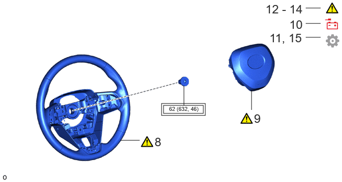
| Procedure | Part Name Code |
|
|
|
|
|---|---|---|---|---|---|
| 8 | STEERING WHEEL ASSEMBLY | 45100 | (202307,999999,_54,_112606,_0503315,RM100000002BUEZ_01_0068,)
|
- | - |
| 9 | HORN BUTTON ASSEMBLY | 45130 | (202307,999999,_54,_112606,_0503315,RM100000002BUEZ_01_0067,)
|
- | - |
| 10 | CONNECT CABLE TO NEGATIVE AUXILIARY BATTERY TERMINAL | - | - | - | - |
| 11 | UPDATE ECU SECURITY KEY | - | - | - | (202307,999999,_54,_112606,_0503315,RM100000002BUEZ_01_0063,)
|
| 12 | INSPECT SRS WARNING LIGHT | - | (202307,999999,_54,_112606,_0503315,RM100000002BUEZ_01_0071,)
|
- | - |
| 13 | INSPECT HORN BUTTON ASSEMBLY | 45130 | (202307,999999,_54,_112606,_0503315,RM100000002BUEZ_01_0070,)
|
- | - |
| 14 | CHECK STEERING WHEEL CENTER POINT | - | (202307,999999,_54,_112606,_0503315,RM100000002BUEZ_01_0074,)
|
- | - |
| 15 | INITIALIZATION AFTER RECONNECTING AUXILIARY BATTERY TERMINAL | - | - | - | (202307,999999,_54,_112606,_0503315,RM100000002BUEZ_01_0073,)
|

|
Tightening torque for "Major areas involving basic vehicle performance such as moving/turning/stopping" : N*m (kgf*cm, ft.*lbf) | - | - |
CAUTION / NOTICE / HINT
- NOTICE:
- ·
A lock pin is installed to a new steering sensor. Do not remove the lock pin before the steering sensor is installed to the spiral cable sub-assembly.
·After replacing the steering sensor, make sure to perform update ECU security key.
·After performing the update ECU security key procedure, make sure to perform the initialization procedure for when the cable has been disconnected and reconnected to the negative (-) auxiliary battery terminal.
PROCEDURE

 84306
1.INSPECT SPIRAL CABLE SUB-ASSEMBLY
84306
1.INSPECT SPIRAL CABLE SUB-ASSEMBLY
89245B
2.INSTALL STEERING SENSOR

| *a | Guide | *b | Pin |
| *c | Lock Pin | - | - |
Align the 2 pins and 2 guides, and engage the 6 claws to install the steering sensor to the spiral cable sub-assembly.
- NOTICE:
- ·
Do not remove the lock pin before the steering sensor is installed to the spiral cable sub-assembly.
·Do not damage the pins of the spiral cable sub-assembly or guides of the steering sensor.
·The spiral cable sub-assembly can be rotated up to 30° even when the interlock is engaged. Therefore, make sure that both guides are aligned properly when installing the steering sensor to the spiral cable sub-assembly.
Remove the lock pin from the steering sensor.
3.PLACE FRONT WHEELS FACING STRAIGHT AHEAD
4.INSTALL SPIRAL CABLE WITH SENSOR SUB-ASSEMBLY
45286B
5.INSTALL UPPER STEERING COLUMN COVER
45287
6.INSTALL LOWER STEERING COLUMN COVER
84306
7.ADJUST SPIRAL CABLE WITH SENSOR SUB-ASSEMBLY
45100
8.INSTALL STEERING WHEEL ASSEMBLY
45130
9.INSTALL HORN BUTTON ASSEMBLY
10.CONNECT CABLE TO NEGATIVE AUXILIARY BATTERY TERMINAL
11. UPDATE ECU SECURITY KEY
- HINT:
-
When the steering sensor is replaced with a new one, ECU security key is necessary.
12.INSPECT SRS WARNING LIGHT
45130
13.INSPECT HORN BUTTON ASSEMBLY
14.CHECK STEERING WHEEL CENTER POINT
15. INITIALIZATION AFTER RECONNECTING AUXILIARY BATTERY TERMINAL
- HINT:
-
When disconnecting and reconnecting the auxiliary battery, there is an automatic learning function that completes learning when the respective system is used.