BRAKE CONTROL / DYNAMIC CONTROL SYSTEMS BRAKE ACTUATOR(for HEV Model) INSTALLATION
CAUTION / NOTICE / HINT
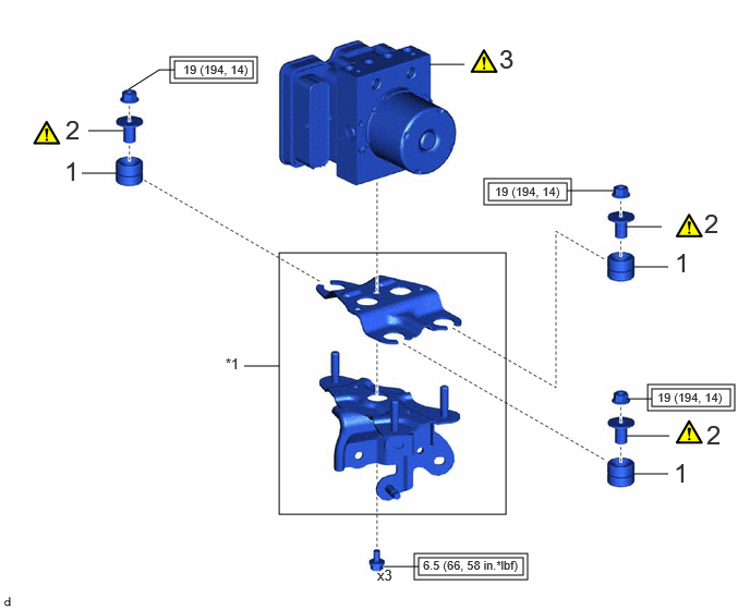
| Procedure | Part Name Code | 
|

|

|
|
|---|---|---|---|---|---|
| 1 | BRAKE ACTUATOR BRACKET CUSHION | 44547B | - | - | - |
| 2 | NO. 1 BRAKE ACTUATOR CASE COLLAR | 44521A | ( 202307,999999,_54,_112606,_0604462,RM100000002BUEN_01_0123,) 202307,999999,_54,_112606,_0604462,RM100000002BUEN_01_0123,)
|
- | - |
| 3 | BRAKE ACTUATOR ASSEMBLY | 44510 | (202307,999999,_54,_112606,_0604462,RM100000002BUEN_01_0103,)
|
- | - |
| *1 | BRAKE ACTUATOR BRACKET ASSEMBLY | - | - |

|
Tightening torque for "Major areas involving basic vehicle performance such as moving/turning/stopping" : N*m (kgf*cm, ft.*lbf) | - | - |
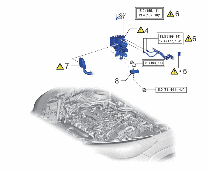
| Procedure | Part Name Code |
|
|
|
|
|---|---|---|---|---|---|
| 4 | BRAKE ACTUATOR WITH BRACKET | - | (202307,999999,_54,_112606,_0604462,RM100000002BUEN_01_0102,)
|
- | - |
| 5 | NO. 1 BRAKE TUBE CLAMP | 47371A | (202307,999999,_54,_112606,_0604462,RM100000002BUEN_01_0131,)
|
- | - |
| 6 | CONNECT BRAKE LINE | - | (202307,999999,_54,_112606,_0604462,RM100000002BUEN_01_0118,)
|
- | - |
| 7 | ENGINE ROOM MAIN WIRE | - | (202307,999999,_54,_112606,_0604462,RM100000002BUEN_01_0130,)
|
- | - |
| 8 | NO. 5 DASH PANEL INSULATOR PLATE | 55228 | - | - | - |
|
|
Tightening torque for "Major areas involving basic vehicle performance such as moving/turning/stopping" : N*m (kgf*cm, ft.*lbf) | 
|
N*m (kgf*cm, ft.*lbf): Specified torque |
| * | For use with a union nut wrench | ● | Non-reusable part |
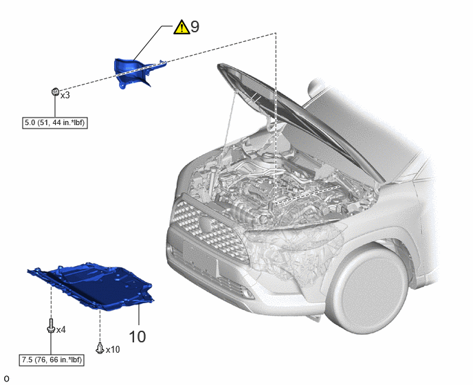
| Procedure | Part Name Code |
|
|
|
|
|---|---|---|---|---|---|
| 9 | DASH PANEL HEAT INSULATOR | - | (202307,999999,_54,_112606,_0604462,RM100000002BUEN_01_0128,)
|
- | - |
| 10 | NO. 1 ENGINE UNDER COVER ASSEMBLY | 51410 | - | - | - |
|
|
N*m (kgf*cm, ft.*lbf): Specified torque | - | - |
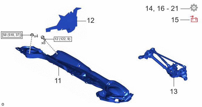
| Procedure | Part Name Code |
|
|
|
|
|---|---|---|---|---|---|
| 11 | OUTER COWL TOP PANEL SUB-ASSEMBLY | 55701J | - | - | - |
| 12 | NO. 1 HEATER AIR DUCT SPLASH SHIELD SEAL | 55737B | - | - | - |
| 13 | WINDSHIELD WIPER MOTOR AND LINK ASSEMBLY | - | - | - | - |
| 14 | BLEED BRAKE LINE | - | - | - | (202307,999999,_54,_112606,_0604462,RM100000002BUEN_01_0108,)
|
| 15 | CONNECT CABLE TO NEGATIVE BATTERY TERMINAL | - | - | - | - |
| 16 | UPDATE ECU SECURITY KEY | - | - | - | (202307,999999,_54,_112606,_0604462,RM100000002BUEN_01_0117,)
|
| 17 | PERFORM BRAKE SYSTEM CALIBRATION | - | - | - | (202307,999999,_54,_112606,_0604462,RM100000002BUEN_01_0107,)
|
| 18 | INSPECT BRAKE ACTUATOR USING GTS | - | - | - | (202307,999999,_54,_112606,_0604462,RM100000002BUEN_01_0105,)
|
| 19 | PERFORM INITIALIZATION | - | - | - | (202307,999999,_54,_112606,_0604462,RM100000002BUEN_01_0120,)
|
| 20 | INITIALIZATION AFTER RECONNECTING AUXILIARY BATTERY TERMINAL | - | - | - | (202307,999999,_54,_112606,_0604462,RM100000002BUEN_01_0119,)
|
| 21 | CHECK AND CLEAR DTCS | - | - | - | (202307,999999,_54,_112606,_0604462,RM100000002BUEN_01_0104,)
|
|
|
Tightening torque for "Major areas involving basic vehicle performance such as moving/turning/stopping" : N*m (kgf*cm, ft.*lbf) |
|
N*m (kgf*cm, ft.*lbf): Specified torque |
CAUTION / NOTICE / HINT
- NOTICE:
- ·
After replacing the brake actuator assembly, make sure to perform update ECU security key.
·After performing the update ECU security key procedure, make sure to perform the initialization procedure for when the cable has been disconnected and reconnected to the negative (-) auxiliary battery terminal.
- HINT:
-
The parking brake indicator light blinks (red) when the ignition switch is turned to ON after replacing the brake actuator assembly. Operate the electric parking brake switch assembly to turn off the parking brake indicator light.
PROCEDURE

 44547B
1.INSTALL BRAKE ACTUATOR BRACKET CUSHION
44547B
1.INSTALL BRAKE ACTUATOR BRACKET CUSHION
44521A
2.INSTALL NO. 1 BRAKE ACTUATOR CASE COLLAR
|
|
|
- Torque:
- 19 N*m (194 kgf*cm, 14 ft.*lbf)
44510
3.INSTALL BRAKE ACTUATOR ASSEMBLY
|
|
|
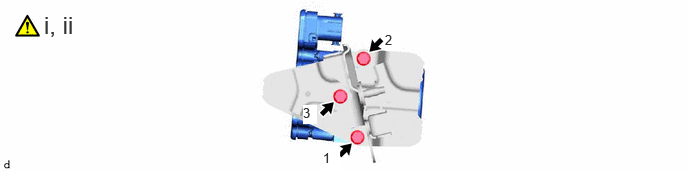
Temporarily install the brake actuator assembly with the 3 bolts.
Fully tighten the 3 bolts in the order shown in the illustration.
- Torque:
- 6.5 N*m (66 kgf*cm, 58 in.*lbf)
4.INSTALL BRAKE ACTUATOR WITH BRACKET
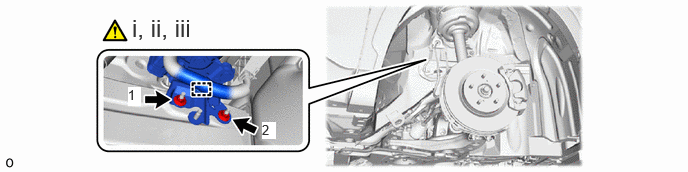
Temporarily install the brake actuator with bracket to the vehicle body with the 2 nuts.
- NOTICE:
- ·
Do not kink or damage the brake lines.
·Do not allow any foreign matter such as dirt or dust to enter the brake lines from the connecting parts.
·Be careful not to allow any brake fluid to enter the connector.
·Do not hold the brake actuator assembly by the connector.
·Do not drop the brake actuator with bracket when carrying it.
- HINT:
-
Install the brake actuator with bracket while avoiding the brake lines.
Fully tighten the 2 nuts in the order shown in the illustration.
- Torque:
- 19 N*m (194 kgf*cm, 14 ft.*lbf)
Engage the clamp to install the engine room main wire.
47371A
5.INSTALL NO. 1 BRAKE TUBE CLAMP
|
|
|
6.CONNECT BRAKE LINE
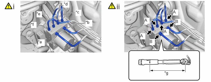
| *a | From 1st Chamber of Brake Master Cylinder Sub-assembly | *b | From 2nd Chamber of Brake Master Cylinder Sub-assembly |
| *c | To Front Wheel Cylinder Assembly RH | *d | To Rear Wheel Cylinder Assembly LH |
| *e | To Rear Wheel Cylinder Assembly RH | *f | To Front Wheel Cylinder Assembly LH |
| *g | Torque Wrench Fulcrum Length | - | - |
Temporarily tighten each brake line to the correct position on the brake actuator assembly as shown in the illustration.
- NOTICE:
- ·
Do not kink or damage the brake line.
·Do not allow any foreign matter such as dirt or dust to enter the brake line from the connecting parts.
Using a union nut wrench, connect the 6 brake lines to the brake actuator assembly.
- Torque:
- Specified tightening torque (A) : 15.2 N*m (155 kgf*cm, 11 ft.*lbf)
- Specified tightening torque (B) : 19.5 N*m (199 kgf*cm, 14 ft.*lbf)
- NOTICE:
- ·
Do not kink or damage the brake lines.
·Do not allow the brake lines to twist or interfere with other parts or the vehicle body during tightening.
·Do not allow any foreign matter such as dirt or dust to enter the brake lines from the connecting parts.
- HINT:
- ·
Calculate the torque wrench reading when changing the fulcrum length of the torque wrench.
·When using a union nut wrench (fulcrum length of 22 mm (0.866 in.)) + torque wrench (fulcrum length of 162 mm (6.38 in.)):
(A): 13.4 N*m (137 kgf*cm, 10 ft.*lbf)
·When using a union nut wrench (fulcrum length of 20 mm (0.787 in.)) + torque wrench (fulcrum length of 162 mm (6.38 in.)):
(B): 17.4 N*m (177 kgf*cm, 13 ft.*lbf)
7.CONNECT ENGINE ROOM MAIN WIRE


|
Lock the lock lever | 
|
Connect the connector |
Connect the connector to the brake actuator assembly and lock the lock lever.
- NOTICE:
- ·
Make sure that the connector is locked securely.
·Make sure that the actuator connector can be connected smoothly.
·Do not allow water, oil or dirt to enter the connector.
55228
8.INSTALL NO. 5 DASH PANEL INSULATOR PLATE
- Torque:
- 5.0 N*m (51 kgf*cm, 44 in.*lbf)
9.INSTALL DASH PANEL HEAT INSULATOR
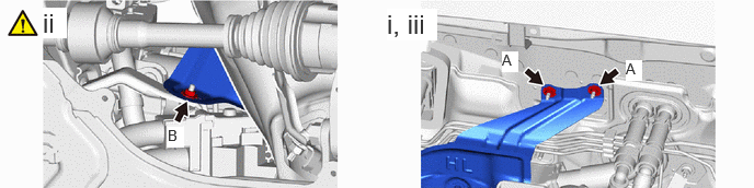
Temporarily install the dash panel heat insulator to the vehicle body with the 2 nuts (A).
Install the nut (B).
- Torque:
- 5.0 N*m (51 kgf*cm, 44 in.*lbf)
Tighten the 2 nuts (A).
- Torque:
- 5.0 N*m (51 kgf*cm, 44 in.*lbf)
51410
10.INSTALL NO. 1 ENGINE UNDER COVER ASSEMBLY
55701J
11.INSTALL OUTER COWL TOP PANEL SUB-ASSEMBLY
55737B
12.INSTALL NO. 1 HEATER AIR DUCT SPLASH SHIELD SEAL
13.INSTALL WINDSHIELD WIPER MOTOR AND LINK ASSEMBLY
14.BLEED BRAKE LINE
15.CONNECT CABLE TO NEGATIVE BATTERY TERMINAL
16. UPDATE ECU SECURITY KEY
- HINT:
-
Perform this procedure only when replacement of the brake actuator assembly is necessary.
17.PERFORM BRAKE SYSTEM CALIBRATION
18.INSPECT BRAKE ACTUATOR USING GTS
19. PERFORM INITIALIZATION
- HINT:
-
The parking brake indicator light blinks (red) when the ignition switch is turned to ON after replacing the brake actuator assembly. Operate the electric parking brake switch assembly to turn off the parking brake indicator light.
20. INITIALIZATION AFTER RECONNECTING AUXILIARY BATTERY TERMINAL
- HINT:
-
When disconnecting and reconnecting the auxiliary battery, there is an automatic learning function that completes learning when the respective system is used.