HYBRID / BATTERY CONTROL HYBRID CONTROL SYSTEM Drive Start Control
DESCRIPTION
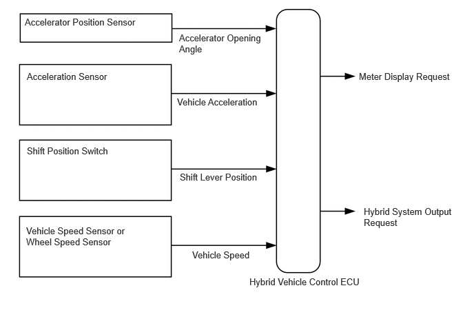
The drive start control is controlled by the hybrid vehicle control ECU.
If the hybrid vehicle control ECU determines that the shift lever and accelerator pedal are operated abnormally, hybrid system output is restricted and, when necessary, a warning is displayed on the combination meter assembly.
CAUTION / NOTICE / HINT
- HINT:
-
Even if the accelerator pedal position is maintained, the hybrid system output may increase when driving uphill and decrease when driving downhill. This is due to drive start control controlling the hybrid system output, and is not a malfunction.
PROCEDURE
Check if the customer operated the vehicle in a way that would cause the drive start control to operate.
Pattern A (When all of the following conditions are met, control starts.)
The accelerator pedal is open by approximately 1/5 or more.
The shift lever is moved from P to any forward position D (Including other forward shift positions) or R.
Pattern B (When all of the following conditions are met, control starts.)
The accelerator pedal is open by approximately 1/5 or more.
The shift lever is moved from R to any forward position D (Including other forward shift positions), any forward position D (Including other forward shift positions) to R, or N to R.
- HINT:
-
Depending on the situation, the shift position may not be changed.
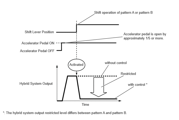
Hybrid system output is restricted.
The accelerator pedal is released.
The shift lever is in P or N.
- HINT:
- ·
The hybrid system output restricted level differs between Pattern A, Pattern B and Reverse control.
·During Shift control or Reverse control, hybrid system output is adjusted based on the road gradient.
·Drive start control is not activated when TRC is turned off.
Control will also not operate under the following conditions. (if equipped)
*When TRAIL mode is on
*When multi-terrain select is selected
- Result:
Result Proceed to Not Performed A Performed B
A
B
Check the DTCs.
Turn the ignition switch off.
- Result:
Result Proceed to DTCs are not output (Hunting) A DTCs are not output (Hesitation/poor acceleration) B DTCs are output C
A
B
C
Read the values displayed on the GTS.
- Chassis > Brake/EPB > Data List
-
Tester Display FR Wheel Speed FL Wheel Speed RR Wheel Speed RL Wheel Speed - 50003 435 13,14,15,16
- Standard:
Tester Display Condition Specified Condition FR Wheel Speed
FL Wheel Speed
RR Wheel Speed
RL Wheel SpeedVehicle stopped 0 km/h (0 mph) Vehicle being driven at constant speed between 16 to 64 km/h (10 to 40 mph) No large fluctuations when driving at a constant speed
- CAUTION:
-
When performing the confirmation driving pattern, obey all speed limits and traffic laws.
- HINT:
-
Data can be captured relatively easily by using the snapshot function in the Data List. Confirm the data after performing the drive test.
Turn the ignition switch off.
- Result:
Proceed to OK NG
OK
NG
Turn the ignition switch to ON (READY).
Read the value displayed on the GTS.
- Powertrain > Hybrid Control > Data List
-
Tester Display Vehicle Speed - 50003 397 12
- Standard:
Inspection Condition Specified Condition Vehicle stopped 0 km/h (0 mph) Vehicle being driven at a constant speed
(16 to 64 km/h (10 to 40 mph))No large fluctuations in displayed speed
- CAUTION:
-
When performing a drive test, obey all speed limits and traffic laws.
- HINT:
-
Data can be captured relatively easily by using the snapshot function in the Data List. Confirm the data after performing the drive test.
Turn the ignition switch off.
- Result:
Proceed to OK NG
OK
NG
Read the value displayed on the GTS.
- Chassis > Brake/EPB > Data List
-
Tester Display Forward and Rearward G - 50003 435 26
- Standard:
Condition Specified Condition During deceleration Changes continuously During acceleration Changes continuously
- CAUTION:
-
When performing a drive test, obey all speed limits and traffic laws.
- HINT:
-
Data can be captured relatively easily by using the snapshot function in the Data List. Confirm the data after performing the drive test.
Turn the ignition switch off.
- Result:
Proceed to OK NG
OK
NG
- Result:
Proceed to OK NG
OK
NG
Read the value displayed on the GTS.
- Powertrain > Hybrid Control > Data List
-
Tester Display Accelerator Position Sensor No.1 Voltage % Accelerator Position Sensor No.2 Voltage % - 50003 397 23,24
- OK:
Condition Specified Condition Accelerator Pedal Released → Depressed Changes continuously
Turn the ignition switch off.
- Result:
Proceed to OK NG
OK
NG