PB10 HYBRID TRANSMISSION / TRANSAXLE HYBRID VEHICLE TRANSAXLE REMOVAL
CAUTION / NOTICE / HINT
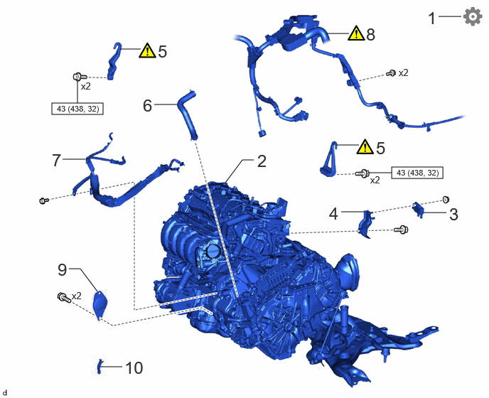
| Procedure | Part Name Code | 
|

|

|
|
|---|---|---|---|---|---|
| 1 | PERFORM RESOLVER INITIALIZATION | - | - | - | ( 202307,999999,_52,_144756,_0603116,RM100000002BO7O_01_0313,) 202307,999999,_52,_144756,_0603116,RM100000002BO7O_01_0313,)
|
| 2 | ENGINE ASSEMBLY WITH TRANSAXLE | - | - | - | - |
| 3 | DIFFERENTIAL PRESSURE SENSOR | 89481B | - | - | - |
| 4 | EMISSION CONTROL VALVE BRACKET | - | - | - | - |
| 5 | ENGINE HANGERS | - | (202307,999999,_52,_144756,_0603116,RM100000002BO7O_01_0299,)
|
- | - |
| 6 | OUTLET NO. 1 INVERTER COOLING HOSE | G922C | - | - | - |
| 7 | NO. 7 ENGINE WIRE | 82127D | - | - | - |
| 8 | ENGINE WIRE | 82121 | (202307,999999,_52,_144756,_0603116,RM100000002BO7O_01_0300,)
|
- | - |
| 9 | STARTER HOLE INSULATOR | 28193 | - | - | - |
| 10 | FLYWHEEL HOUSING SIDE COVER | 11363A | - | - | - |

|
N*m (kgf*cm, ft.*lbf): Specified torque | - | - |
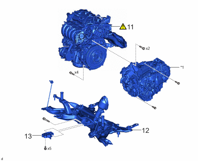
| Procedure | Part Name Code |
|
|
|
|
|---|---|---|---|---|---|
| 11 | ENGINE ASSEMBLY | - | (202307,999999,_52,_144756,_0603116,RM100000002BO7O_01_0310,)
|
- | - |
| 12 | FRONT SUSPENSION CROSSMEMBER SUB-ASSEMBLY | 51201 | - | - | - |
| 13 | NO. 2 ENGINE MOVING CONTROL ROD | 12364B | - | - | - |
| *1 | HYBRID VEHICLE TRANSAXLE ASSEMBLY | - | - |
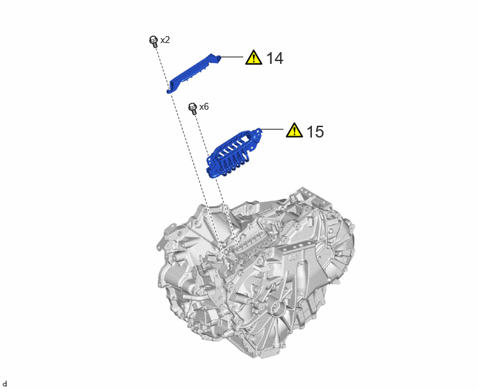
| Procedure | Part Name Code |
|
|
|
|
|---|---|---|---|---|---|
| 14 | TERMINAL CAP | 82823M | (202307,999999,_52,_144756,_0603116,RM100000002BO7O_01_0321,)
|
- | - |
| 15 | MOTOR CABLE | G1148 | (202307,999999,_52,_144756,_0603116,RM100000002BO7O_01_0305,)
|
- | - |
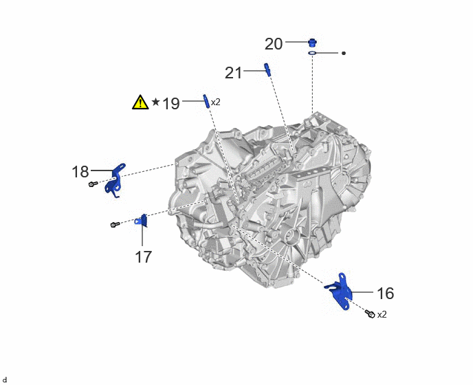
| Procedure | Part Name Code |
|
|
|
|
|---|---|---|---|---|---|
| 16 | NO. 1 TRANSMISSION CONTROL CABLE BRACKET | 33823 | - | - | - |
| 17 | WIRE HARNESS CLAMP BRACKET | - | - | - | - |
| 18 | NO. 1 WATER HOSE CLAMP BRACKET | 16575C | - | - | - |
| 19 | STUD BOLT | - | (202307,999999,_52,_144756,_0603116,RM100000002BO7O_01_0316,)
|
- | - |
| 20 | TRANSAXLE HOUSING PLUG | - | - | - | - |
| 21 | TRANSAXLE BREATHER PLUG | 30900N | - | - | - |
| ● | Non-reusable part | ★ | Precoated part |
CAUTION / NOTICE / HINT
The necessary procedures (adjustment, calibration, initialization, or registration) that must be performed after parts are removed and installed, or replaced during hybrid vehicle transaxle assembly removal/installation are shown below.
| Replaced Part or Performed Procedure | Necessary Procedure | Effect/Inoperative Function when Necessary Procedure not Performed | Link |
|---|---|---|---|
| Hybrid vehicle transaxle assembly | ·
Resolver learning ·
Initialize resolver |
·
DTCs are stored ·
Slight vibration at a vehicle speed of 5 km/h (3 mph) or less ·
Shock or vibration during acceleration |
(202307,999999,_51,_144957,_0604233,RM100000002BW44,)
|
| Front wheel alignment adjustment | Calibration | ·
DTCs are stored ·
ABS warning light illuminates ·
Slip indicator light illuminates ·
VSC disabled or malfunctions |
(202307,999999,_54,_112606,_0608077,RM100000002C79U,)
|
| Suspension, tires, etc. | Parking assist ECU initialization | Panoramic view monitor system | (202201,999999,_56,_111969,_0587004,RM1000000029RN8,)
|
- HINT:
-
When the cable is disconnected / reconnected to the auxiliary battery terminal, systems temporarily stop operating. However, each system has a function that completes learning the first time the system is used.
- ·
Learning completes when vehicle is driven
Effect/Inoperative Function When Necessary Procedures are not Performed Necessary Procedures Link Front camera system Drive the vehicle straight ahead at 15 km/h (10 mph) or more for 1 second or more. ( 202307,999999,_95,_112293,_0586709,RM100000002BSVY,)
·Learning completes when vehicle is operated normally
Effect/Inoperative Function When Necessary Procedures are not Performed Necessary Procedures Link Power door lock control system
·Back door opener
Perform door unlock operation with door control switch or electrical key transmitter sub-assembly switch. ( 202201,999999,_58,_115226,_0510939,RM1000000020BSY,)
Power back door system Fully close the back door by hand.
- HINT:
-
Initialization is not necessary if the above procedures are performed while the back door is closed.
( 202201,999999,_59,_113746,_0504731,RM100000001ZJKP,)
Air conditioning system After the ignition switch is turned to ON, the servo motor standard position is recognized. -
CAUTION / NOTICE / HINT
- CAUTION:
- ·
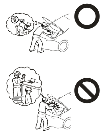
This vehicle has contains high voltage circuits standardized with orange colored wiring and connectors, so follow the instructions in this manual to perform the procedures correctly.
·If the correct procedures are not followed according to the instructions in this manual, there is a danger of electric shock from the high voltage circuits.
·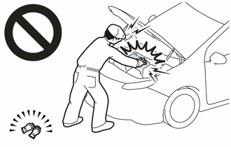
Be sure to wear insulating gloves when working on high voltage wiring or components.
·If work is performed without wearing insulating gloves, there is a danger of electric shock.
·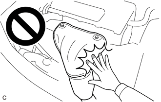
To prevent burns, do not touch the engine, exhaust manifold or other high temperature components while the engine is hot.
·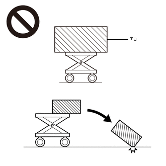 2.219,0.813 2.646,0.813 false 2.698,0.729 3.01,0.927 0.313,0.198 10 false *a
*a An Object Exceeding Weight Limit of Engine Lifter
The engine assembly with transaxle is very heavy. Be sure to follow the procedure described in the repair manual, or the engine lifter may suddenly drop or the engine assembly with transaxle may fall off the engine lifter.
PROCEDURE

 1. PERFORM RESOLVER INITIALIZATION
- NOTICE:
-
If it is necessary to replace the hybrid vehicle transaxle assembly, make sure to perform resolver initialization before starting work.
2.REMOVE ENGINE ASSEMBLY WITH TRANSAXLE
89481B
3.REMOVE DIFFERENTIAL PRESSURE SENSOR
4.REMOVE EMISSION CONTROL VALVE BRACKET
5.INSTALL ENGINE HANGERS
G922C
6.REMOVE OUTLET NO. 1 INVERTER COOLING HOSE

82127D
7.REMOVE NO. 7 ENGINE WIRE

82121
8.DISCONNECT ENGINE WIRE

| *a | Motor Resolver, Generator Resolver and Transmission Fluid Temperature Sensor Connector | *b | Motor Temperature Sensor and Generator Temperature Sensor Connector |
| *c | Shift Lever Position Sensor Connector | - | - |
Disconnect the motor resolver, generator resolver and transmission fluid temperature sensor connector.
Disconnect the motor temperature sensor and generator temperature sensor connector.
Disconnect the shift lever position sensor connector.
- NOTICE:
-
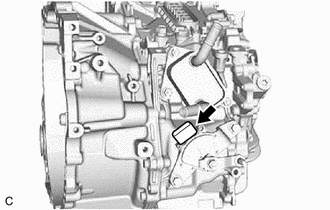
-
After disconnecting the engine wire, cover the connector of the shift lever position sensor with tape (non-residue type) or equivalent to prevent the entry of foreign matter or water.
Disengage the 3 clamps to disconnect the engine wire.
Disengage the 5 clamps to disconnect the engine wire.
Remove the 2 bolts to disconnect the engine wire from the hybrid vehicle transaxle assembly.
28193
9.REMOVE STARTER HOLE INSULATOR

11363A
10.REMOVE FLYWHEEL HOUSING SIDE COVER

11.REMOVE ENGINE ASSEMBLY
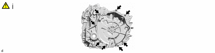
Remove the 8 bolts and engine assembly from the hybrid vehicle transaxle assembly.
- NOTICE:
- ·
To avoid damaging the knock pins, do not pry between the hybrid vehicle transaxle assembly and engine assembly.
·To prevent the splines of the transmission input damper assembly from becoming misaligned, do not allow the hybrid vehicle transaxle assembly to hit the transmission input damper assembly during engine assembly removal and installation.
51201
12.REMOVE FRONT SUSPENSION CROSSMEMBER SUB-ASSEMBLY

12364B
13.REMOVE NO. 2 ENGINE MOVING CONTROL ROD

82823M
14.REMOVE TERMINAL CAP
G1148
15.REMOVE MOTOR CABLE
33823
16.REMOVE NO. 1 TRANSMISSION CONTROL CABLE BRACKET

17.REMOVE WIRE HARNESS CLAMP BRACKET

16575C
18.REMOVE NO. 1 WATER HOSE CLAMP BRACKET

19.REMOVE STUD BOLT
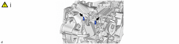
Using an E10 "TORX" socket wrench, remove the 2 stud bolts from the hybrid vehicle transaxle assembly.
20.REMOVE TRANSAXLE HOUSING PLUG

30900N
21.REMOVE TRANSAXLE BREATHER PLUG
- HINT:
-
Perform this procedure only when replacement of the transaxle breather plug is necessary.