HEATING / AIR CONDITIONING AIR CONDITIONING SYSTEM(for HEV Model) B143A87 Lost Communication with Air Inlet Damper Control Servo Motor LIN Missing Message
DESCRIPTION
The air conditioning harness assembly and No. 1 air conditioning radiator damper servo sub-assembly connect the air conditioning amplifier assembly and the No. 1 blower damper servo sub-assembly. The air conditioning amplifier assembly supplies power and sends operation instructions to No. 1 blower damper servo sub-assembly through the air conditioning harness assembly and No. 1 air conditioning radiator damper servo sub-assembly. The No. 1 blower damper servo sub-assembly sends pulse signals to inform the air conditioning amplifier assembly of the damper position.
| DTC No. | Detection Item | DTC Detection Condition | Trouble Area | Memory |
|---|---|---|---|---|
| B143A87 | Lost Communication with Air Inlet Damper Control Servo Motor LIN Missing Message | Diagnosis Condition:
Ignition switch ON Malfunction Status: Error or lost communication with No. 1 blower damper servo sub-assembly Detection Time: Continuously for 10 seconds or more |
·
No. 1 blower damper servo sub-assembly ·
Air conditioning harness assembly |
Memorized |
| Vehicle Condition | |||
|---|---|---|---|
| Pattern 1 | Pattern 2 | ||
| Diagnosis Condition | Ignition switch ON | ○ | ○ |
| Malfunction | Error communication with No. 1 blower damper servo sub-assembly | ○ | - |
| Lost communication with No. 1 blower damper servo sub-assembly | - | ○ | |
| Detection Time | Continuously for 10 seconds or more | Continuously for 10 seconds or more | |
| Trip Count | 1 trip | 1 trip | |
- HINT:
-
If the conditions of either of these patterns are detected, a DTC will be stored.
WIRING DIAGRAM
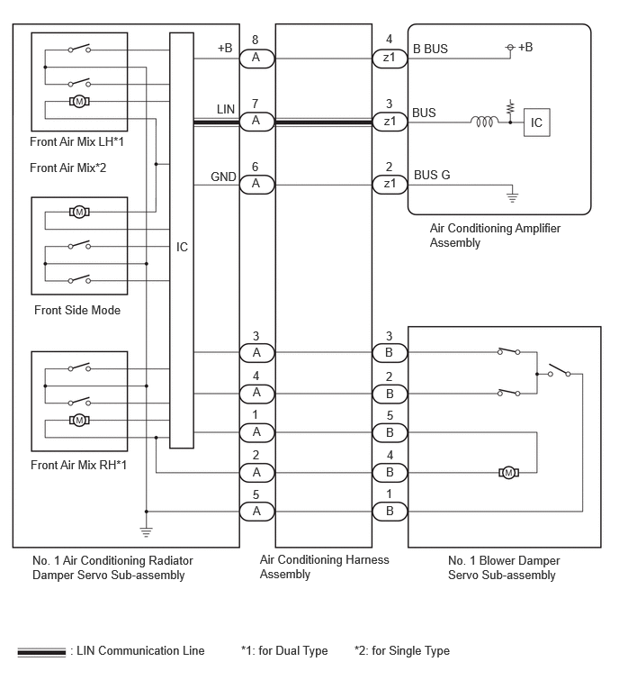
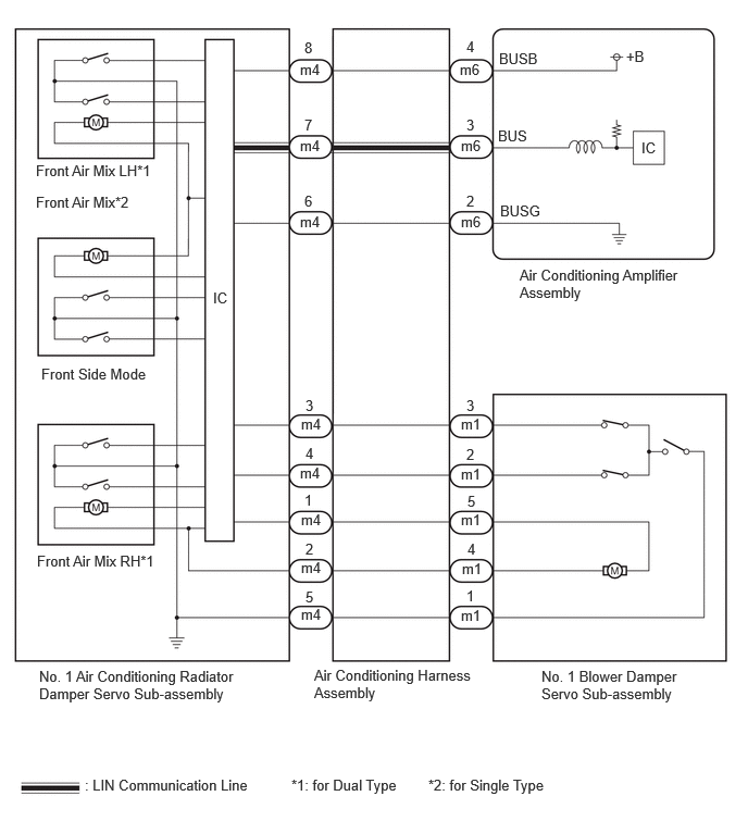
PROCEDURE
Check for DTCs.
- Body Electrical > Air Conditioner > Trouble Codes
- 50001 450
- Result:
Result Proceed to B142A88 is output A B142A88 is not output
(w/ Rear Air Duct)B B142A88 is not output
(w/o Rear Air Duct)C
A
B
C
Disconnect the A No. 1 air conditioning radiator damper servo sub-assembly connector.
Disconnect the B No. 1 blower damper servo sub-assembly connector.
Measure the resistance according to the value(s) in the table below.
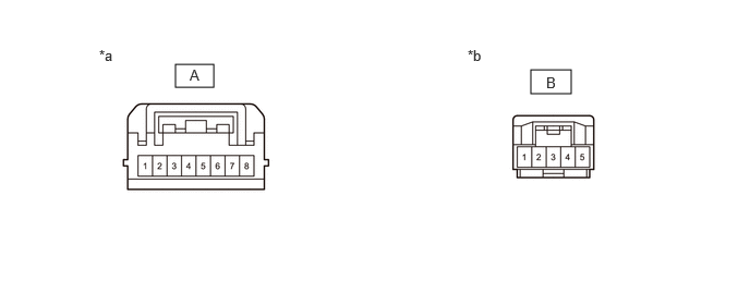
| *a | Front view of wire harness connector
(to No. 1 Air Conditioning Radiator Damper Servo Sub-assembly) |
*b | Front view of wire harness connector
(to No. 1 Blower Damper Servo Sub-assembly) |
- Standard Resistance:
Tester Connection Condition Specified Condition A-1 - B-5 Always Below 1 Ω A-2 - B-4 Always Below 1 Ω A-3 - B-3 Always Below 1 Ω A-4 - B-2 Always Below 1 Ω A-5 - B-1 Always Below 1 Ω A-1 or B-5 - Other terminals and body ground Always 10 kΩ or higher A-2 or B-4 - Other terminals and body ground Always 10 kΩ or higher A-3 or B-3 - Other terminals and body ground Always 10 kΩ or higher A-4 or B-2 - Other terminals and body ground Always 10 kΩ or higher
- Result:
Proceed to OK NG
OK
NG
Disconnect the m4 No. 1 air conditioning radiator damper servo sub-assembly connector.
Disconnect the m1 No. 1 blower damper servo sub-assembly connector.
Measure the resistance according to the value(s) in the table below.
- Standard Resistance:
Tester Connection Condition Specified Condition m4-1 - m1-5 Always Below 1 Ω m4-2 - m1-4 Always Below 1 Ω m4-3 - m1-3 Always Below 1 Ω m4-4 - m1-2 Always Below 1 Ω m4-5 - m1-1 Always Below 1 Ω m4-1 or m1-5 - Other terminals and body ground Always 10 kΩ or higher m4-2 or m1-4 - Other terminals and body ground Always 10 kΩ or higher m4-3 or m1-3 - Other terminals and body ground Always 10 kΩ or higher m4-4 or m1-2 - Other terminals and body ground Always 10 kΩ or higher
- Result:
Proceed to OK NG
OK
NG