RM38T0EC _56 Audio / Visual / Telematics _111966 AUDIO / VIDEO _0589552 AUDIO AND VISUAL SYSTEM(Production Date from 2023/04) J

AUDIO / VIDEO  AUDIO AND VISUAL SYSTEM(Production Date from 2023/04)  Speaker Circuit  


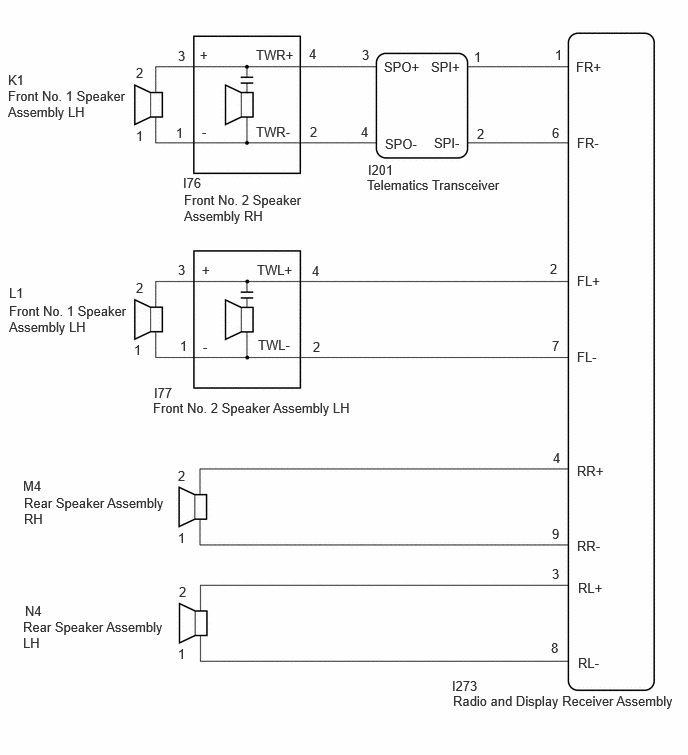
WIRING DIAGRAM
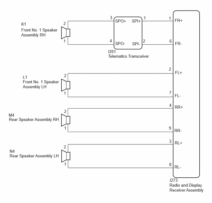
for 4 Speakers
E509823E07
0.719,0.729 1.031,0.927 0.313,0.198 10 false K1 0.719,0.927 2,1.344 1.281,0.417 10 false Front No. 1 Speaker Assembly RH 2.146,0.708 2.417,0.885 0.271,0.177 10 false 2 2.146,1.302 2.417,1.479 0.271,0.177 10 false 1 3.719,0.51 4,0.688 0.281,0.177 10 false 3 3.708,1.292 3.979,1.469 0.271,0.177 10 false 4 3.896,0.625 4.344,0.802 0.448,0.177 10 false SPO+ 4.458,0.625 4.906,0.802 0.448,0.177 10 false SPI+ 3.896,1.385 4.344,1.563 0.448,0.177 10 false SPO- 5.906,0.604 6.354,0.781 0.448,0.177 10 false FR+ 4.469,1.396 4.917,1.573 0.448,0.177 10 false SPI- 4.854,0.521 5.125,0.698 0.271,0.177 10 false 1 4.833,1.302 5.104,1.479 0.271,0.177 10 false 2 5.708,0.531 5.979,0.708 0.271,0.177 10 false 1 5.729,1.302 6,1.479 0.271,0.177 10 false 6 5.917,1.385 6.365,1.563 0.448,0.177 10 false FR- 3.656,1.656 4.042,1.844 0.385,0.188 10 false I201 3.656,1.813 5.177,2.156 1.521,0.344 10 false Telematics Transceiver 0.771,2.677 2.052,3.094 1.281,0.417 10 false Front No. 1 Speaker Assembly LH 0.302,3.948 2.083,4.313 1.781,0.365 10 false Rear Speaker Assembly RH 0.323,5.177 2.063,5.625 1.74,0.448 10 false Rear Speaker Assembly LH 0.771,2.521 1.083,2.719 0.313,0.198 10 false L1 0.292,3.802 0.604,4 0.313,0.198 10 false M4 0.323,5.021 0.635,5.219 0.313,0.198 10 false N4 2.167,2.469 2.438,2.646 0.271,0.177 10 false 2 2.167,3.677 2.438,3.854 0.271,0.177 10 false 2 2.156,4.875 2.427,5.052 0.271,0.177 10 false 2 2.156,3.063 2.427,3.24 0.271,0.177 10 false 1 2.167,4.24 2.438,4.417 0.271,0.177 10 false 1 2.167,5.458 2.438,5.635 0.271,0.177 10 false 1 5.708,2.25 5.979,2.427 0.271,0.177 10 false 2 5.719,3.042 5.99,3.219 0.271,0.177 10 false 7 5.719,3.469 5.99,3.646 0.271,0.177 10 false 4 5.708,4.24 5.979,4.417 0.271,0.177 10 false 9 5.719,4.688 5.99,4.865 0.271,0.177 10 false 3 5.719,5.469 5.99,5.646 0.271,0.177 10 false 8 5.917,2.365 6.365,2.542 0.448,0.177 10 false FL+ 5.906,3.146 6.354,3.323 0.448,0.177 10 false FL- 5.906,3.531 6.354,3.708 0.448,0.177 10 false RR+ 5.896,4.323 6.344,4.5 0.448,0.177 10 false RR- 5.906,4.74 6.354,4.917 0.448,0.177 10 false RL+ 5.896,5.552 6.344,5.729 0.448,0.177 10 false RL- 5.729,6.167 6.917,6.635 1.188,0.469 10 false Radio and Display Receiver Assembly 5.74,6 6.125,6.188 0.385,0.188 10 false I273

for 6 Speakers
E509816E06
0.094,2.969 0.406,3.167 0.313,0.198 10 false L1 0.094,3.156 1.344,3.677 1.25,0.521 10 false Front No. 1 Speaker Assembly LH 1.417,0.677 1.625,0.875 0.208,0.198 10 false 2 1.417,1.333 1.625,1.531 0.208,0.198 10 false 1 1.417,2.917 1.625,3.115 0.208,0.198 10 false 2 1.396,3.563 1.604,3.76 0.208,0.198 10 false 1 1.875,3.521 2.083,3.719 0.208,0.198 10 false 1 1.854,2.729 2.063,2.927 0.208,0.198 10 false 3 3.26,3.531 3.469,3.729 0.208,0.198 10 false 2 3.25,2.74 3.458,2.938 0.208,0.198 10 false 4 3.219,0.479 3.427,0.677 0.208,0.198 10 false 4 3.229,1.292 3.438,1.49 0.208,0.198 10 false 2 1.854,0.5 2.063,0.698 0.208,0.198 10 false 3 1.833,1.302 2.042,1.5 0.208,0.198 10 false 1 0.083,0.75 0.396,0.948 0.313,0.198 10 false K1 0.083,0.917 1.333,1.438 1.25,0.521 10 false Front No. 1 Speaker Assembly LH 2.667,1.292 3.135,1.479 0.469,0.188 10 false TWR- 2.667,0.49 3.135,0.677 0.469,0.188 10 false TWR+ 2.083,0.49 2.292,0.688 0.208,0.198 10 false + 2.104,1.292 2.313,1.49 0.208,0.198 10 false - 2.104,2.729 2.313,2.927 0.208,0.198 10 false + 2.115,3.531 2.323,3.729 0.208,0.198 10 false - 3.771,0.49 3.979,0.688 0.208,0.198 10 false 3 3.76,1.292 3.969,1.49 0.208,0.198 10 false 4 4.938,0.51 5.146,0.708 0.208,0.198 10 false 1 4.969,1.313 5.177,1.51 0.208,0.198 10 false 2 4,0.615 4.469,0.802 0.469,0.188 10 false SPO+ 4.49,0.615 4.958,0.802 0.469,0.188 10 false SPI+ 4.521,1.406 4.99,1.594 0.469,0.188 10 false SPI- 4.01,1.417 4.479,1.604 0.469,0.188 10 false SPO- 1.906,1.823 2.375,2.01 0.469,0.188 10 false I76 1.917,2 3.208,2.385 1.292,0.385 10 false Front No. 2 Speaker Assembly RH 3.833,1.688 4.292,1.875 0.458,0.188 10 false I201 3.823,1.844 5.365,2.115 1.542,0.271 10 false Telematics Transceiver 6,0.615 6.458,0.802 0.458,0.188 10 false FR+ 6.01,1.406 6.469,1.594 0.458,0.188 10 false FR- 6.01,2.844 6.469,3.031 0.458,0.188 10 false FL+ 6.01,3.635 6.469,3.823 0.458,0.188 10 false FL- 1.854,4.875 2.063,5.073 0.208,0.198 10 false 2 1.854,5.521 2.063,5.719 0.208,0.198 10 false 1 1.854,6.729 2.063,6.927 0.208,0.198 10 false 1 1.865,6.083 2.073,6.281 0.208,0.198 10 false 2 0.24,4.979 0.552,5.177 0.313,0.198 10 false M4 0.25,5.156 1.76,5.667 1.51,0.51 10 false Rear Speaker Assembly RH 0.26,6.281 0.573,6.479 0.313,0.198 10 false N4 0.24,6.448 1.75,6.958 1.51,0.51 10 false Rear Speaker Assembly LH 5.75,5.896 5.958,6.094 0.208,0.198 10 false 3 5.74,6.667 5.948,6.865 0.208,0.198 10 false 8 5.76,4.688 5.969,4.885 0.208,0.198 10 false 4 5.75,5.479 5.958,5.677 0.208,0.198 10 false 9 6.01,4.823 6.469,5.01 0.458,0.188 10 false RR+ 6.01,5.604 6.469,5.792 0.458,0.188 10 false RR- 6.021,6.042 6.479,6.229 0.458,0.188 10 false RL+ 6.021,6.823 6.479,7.01 0.458,0.188 10 false RL- 4.708,7.063 5.167,7.25 0.458,0.188 10 false I273 4.719,7.219 7.156,7.521 2.438,0.302 10 false Radio and Display Receiver Assembly 2.677,2.729 3.146,2.917 0.469,0.188 10 false TWL+ 2.688,3.51 3.156,3.698 0.469,0.188 10 false TWL- 5.781,0.49 5.99,0.688 0.208,0.198 10 false 1 5.75,1.302 5.958,1.5 0.208,0.198 10 false 6 5.729,2.719 5.938,2.917 0.208,0.198 10 false 2 5.75,3.521 5.958,3.719 0.208,0.198 10 false 7 1.594,4.167 3.865,4.385 2.271,0.219 10 false Front No. 2 Speaker Assembly LH 1.604,4.01 2.073,4.198 0.469,0.188 10 false I77

CAUTION / NOTICE / HINT

NOTICE:
·

When replacing the telematics transceiver, make sure to replace it with a new one.

·

Depending on the parts that are replaced during vehicle inspection or maintenance, performing initialization, registration or calibration may be needed.

Click hereAudio / Visual / Telematics>AUDIO / VIDEO>AUDIO AND VISUAL SYSTEM (Production Date from 2023/04)>PRECAUTION


PROCEDURE

1.CHECK MODEL
a.

Choose the model to be inspected.


Result:
Result Proceed to
for 4 Speakers A
for 6 Speakers B


A

2.CHECK SPEAKER (OPERATION CHECK)

B

9.CHECK SPEAKER (OPERATION CHECK)
2.CHECK SPEAKER (OPERATION CHECK)

b.

Select "Failure Diagnosis" from the "Service Menu" screen.


c.

Select "System Check" from the "Failure Diagnosis" screen.

d.
E392137

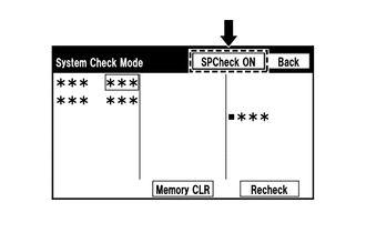
Select "SPCheck ON" from the "System Check Mode" screen and perform speaker check.

OK:

Each speaker outputs sound from the selected audio source properly.


Result:
Result Proceed to
Front No. 1 speaker assembly does not outputs sound A
Rear speaker assembly does not outputs sound B


A

3.CHECK HARNESS AND CONNECTOR (RADIO AND DISPLAY RECEIVER ASSEMBLY - FRONT NO. 1 SPEAKER ASSEMBLY LH, TELEMATICS TRANSCEIVER)

B

7.CHECK HARNESS AND CONNECTOR (RADIO AND DISPLAY RECEIVER ASSEMBLY - REAR SPEAKER ASSEMBLY)
3.CHECK HARNESS AND CONNECTOR (RADIO AND DISPLAY RECEIVER ASSEMBLY - FRONT NO. 1 SPEAKER ASSEMBLY LH, TELEMATICS TRANSCEIVER)
a.

Disconnect the I273 radio and display receiver assembly connector.


b.

Disconnect the L1 front No. 1 speaker assembly LH connector.


c.

Disconnect the I201 telematics transceiver connector.


d.

Measure the resistance according to the value (s) in the table below.

Standard Resistance:
Tester Connection Condition Specified Condition
I273-1 (FR+) - I201-1 (SPI+) Always Below 1 Ω
I273-6 (FR-) - I201-2 (SPI-) Always Below 1 Ω
I273-2 (FL+) - L1-2 Always Below 1 Ω
I273-7 (FL-) - L1-1 Always Below 1 Ω
I273-1 (FR+) - Body ground Always 10 kΩ or higher
I273-6 (FR-) - Body ground Always 10 kΩ or higher
I273-2 (FL+) - Body ground Always 10 kΩ or higher
I273-7 (FL-) - Body ground Always 10 kΩ or higher


Result:
Proceed to
OK
NG


OK

4.CHECK HARNESS AND CONNECTOR (TELEMATICS TRANSCEIVER - FRONT NO. 1 SPEAKER ASSEMBLY RH)

NG

REPAIR OR REPLACE HARNESS OR CONNECTOR

4.CHECK HARNESS AND CONNECTOR (TELEMATICS TRANSCEIVER - FRONT NO. 1 SPEAKER ASSEMBLY RH)
a.

Disconnect the K1 front No. 1 speaker assembly RH connector.


b.

Disconnect the I201 telematics transceiver connector.


c.

Measure the resistance according to the value(s) in the table below.

Standard Resistance:
Tester Connection Condition Specified Condition
K1-2 - I201-3 (SPO+) Always Below 1 Ω
K1-1 - I201-4 (SPO-) Always Below 1 Ω
I201-3 (SPO+) - Body ground Always 10 kΩ or higher
I201-4 (SPO-) - Body ground Always 10 kΩ or higher


Result:
Proceed to
OK
NG


OK

5.INSPECT FRONT NO. 1 SPEAKER ASSEMBLY

NG

REPAIR OR REPLACE HARNESS OR CONNECTOR

5.INSPECT FRONT NO. 1 SPEAKER ASSEMBLY

OK

6.INSPECT TELEMATICS TRANSCEIVER

NG

6.INSPECT TELEMATICS TRANSCEIVER

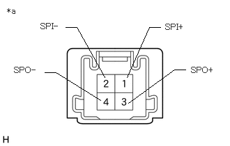
b.
E418548C01
0.979,0.406 1.146,0.406 1.146,0.406 1.563,1.156 false 0.667,1.083 0.833,1.083 0.833,1.083 1.5,1.5 false 2.396,0.406 2.229,0.406 2.229,0.406 1.896,1.156 false 2.771,1.042 2.604,1.042 2.604,1.042 1.917,1.542 false 2.469,0.333 2.917,0.552 0.448,0.219 10 false SPI+ 0.604,0.323 1.052,0.542 0.448,0.219 10 false SPI- 2.854,0.979 3.302,1.198 0.448,0.219 10 false SPO+ 0.208,0.979 0.656,1.198 0.448,0.219 10 false SPO- 0.104,0.094 0.552,0.313 0.448,0.219 10 false *a
*a Component without harness connected
(Telematics Transceiver)


Measure the resistance according to the value(s) in the table below.

Standard Resistance:
Tester Connection Condition Specified Condition
1 (SPI+) - 3 (SPO+) Always Below 1 Ω
2 (SPI-) - 4 (SPO-) Always Below 1 Ω
1 (SPI+) - 2 (SPI-) Always 10 kΩ or higher
3 (SPO+) - 4 (SPO-) Always 10 kΩ or higher


Result:
Proceed to
OK
NG


OK

NG

7.CHECK HARNESS AND CONNECTOR (RADIO AND DISPLAY RECEIVER ASSEMBLY - REAR SPEAKER ASSEMBLY)
a.

Disconnect the I273 radio and display receiver assembly connector.


b.

Disconnect the M4 rear speaker assembly RH connector.


c.

Disconnect the N4 rear speaker assembly LH connectors.


d.

Measure the resistance according to the value(s) in the table below.

Standard Resistance:
Tester Connection Condition Specified Condition
I273-4 (RR+) - M4-2 Always Below 1 Ω
I273-9 (RR-) - M4-1 Always Below 1 Ω
I273-3 (RL+) - N4-2 Always Below 1 Ω
I273-8 (RL-) - N4-1 Always Below 1 Ω
I273-4 (RR+) - Body ground Always 10 kΩ or higher
I273-9 (RR-) - Body ground Always 10 kΩ or higher
I273-3 (RL+) - Body ground Always 10 kΩ or higher
I273-8 (RL-) - Body ground Always 10 kΩ or higher


Result:
Proceed to
OK
NG


OK

8.INSPECT REAR SPEAKER ASSEMBLY

NG

REPAIR OR REPLACE HARNESS AND CONNECTOR

9.CHECK SPEAKER (OPERATION CHECK)

b.

Select "Failure Diagnosis" from the "Service Menu" screen.


c.

Select "System Check" from the "Failure Diagnosis" screen.


d.
E392137

Select "SPCheck ON" from the "System Check Mode" screen and perform speaker check.

OK:

Each speaker outputs sound from the selected audio source properly.


Result:
Result Proceed to
Front No. 1 speaker assembly or front No. 2 speaker assembly does not outputs sound A
Rear speaker assembly does not outputs sound B


A

10.CHECK HARNESS AND CONNECTOR (RADIO AND DISPLAY RECEIVER ASSEMBLY - FRONT NO. 2 SPEAKER ASSEMBLY LH, TELEMATICS TRANSCEIVER)

B

16.CHECK HARNESS AND CONNECTOR (RADIO AND DISPLAY RECEIVER ASSEMBLY - REAR SPEAKER ASSEMBLY)
10.CHECK HARNESS AND CONNECTOR (RADIO AND DISPLAY RECEIVER ASSEMBLY - FRONT NO. 2 SPEAKER ASSEMBLY LH, TELEMATICS TRANSCEIVER)
a.

Disconnect the I273 radio and display receiver assembly connector.


b.

Disconnect the I77 front No. 2 speaker assembly LH connector.


c.

Disconnect the I201 telematics transceiver connector.


d.

Measure the resistance according to the value (s) in the table below.

Standard Resistance:
Tester Connection Condition Specified Condition
I273-1 (FR+) - I201-1 (SPI+) Always Below 1 Ω
I273-6 (FR-) - I201-2 (SPI-) Always Below 1 Ω
I273-2 (FL+) - I77-4 (TWL+) Always Below 1 Ω
I273-7 (FL-) - I77-2 (TWL-) Always Below 1 Ω
I273-1 (FR+) - Body ground Always 10 kΩ or higher
I273-6 (FR-) - Body ground Always 10 kΩ or higher
I273-2 (FL+) - Body ground Always 10 kΩ or higher
I273-7 (FL-) - Body ground Always 10 kΩ or higher


Result:
Proceed to
OK
NG


OK

11.CHECK HARNESS AND CONNECTOR (TELEMATICS TRANSCEIVER - FRONT NO. 2 SPEAKER ASSEMBLY RH)

NG

REPAIR OR REPLACE HARNESS OR CONNECTOR

11.CHECK HARNESS AND CONNECTOR (TELEMATICS TRANSCEIVER - FRONT NO. 2 SPEAKER ASSEMBLY RH)
a.

Disconnect the I76 front No. 2 speaker assembly RH connector.


b.

Disconnect the I201 telematics transceiver connector.


c.

Measure the resistance according to the value(s) in the table below.

Standard Resistance:
Tester Connection Condition Specified Condition
I76-4 (TWR+) - I201-3 (SPO+) Always Below 1 Ω
I76-2 (TWR-) - I201-4 (SPO-) Always Below 1 Ω
I201-3 (SPO+) - Body ground Always 10 kΩ or higher
I201-4 (SPO-) - Body ground Always 10 kΩ or higher


Result:
Proceed to
OK
NG


OK

12.CHECK HARNESS AND CONNECTOR (FRONT NO. 1 SPEAKER ASSEMBLY - FRONT NO. 2 SPEAKER ASSEMBLY)

NG

REPAIR OR REPLACE HARNESS OR CONNECTOR

12.CHECK HARNESS AND CONNECTOR (FRONT NO. 1 SPEAKER ASSEMBLY - FRONT NO. 2 SPEAKER ASSEMBLY)
a.

Disconnect the K1 front No. 1 speaker assembly RH connector.


b.

Disconnect the L1 front No. 1 speaker assembly LH connector.


c.

Disconnect the I76 front No. 2 speaker assembly RH connector.


d.

Disconnect the I77 front No. 2 speaker assembly LH connector.


e.

Measure the resistance according to the value (s) in the table below.

Standard Resistance:
Tester Connection Condition Specified Condition
K1-2 - I76-3 (+) Always Below 1 Ω
K1-1 - I76-1 (-) Always Below 1 Ω
L1-2 - I77-3 (+) Always Below 1 Ω
L1-1 - I77-1 (-) Always Below 1 Ω
K1-2 - Body ground Always 10 kΩ or higher
K1-1 - Body ground Always 10 kΩ or higher
L1-2 - Body ground Always 10 kΩ or higher
L1-1 - Body ground Always 10 kΩ or higher


Result:
Proceed to
OK
NG


OK

13.INSPECT FRONT NO. 1 SPEAKER ASSEMBLY

NG

REPAIR OR REPLACE HARNESS OR CONNECTOR

13.INSPECT FRONT NO. 1 SPEAKER ASSEMBLY

OK

14.INSPECT FRONT NO. 2 SPEAKER ASSEMBLY

NG

15.INSPECT TELEMATICS TRANSCEIVER

b.
E418548C01
0.979,0.406 1.146,0.406 1.146,0.406 1.563,1.156 false 0.667,1.083 0.833,1.083 0.833,1.083 1.5,1.5 false 2.396,0.406 2.229,0.406 2.229,0.406 1.896,1.156 false 2.771,1.042 2.604,1.042 2.604,1.042 1.917,1.542 false 2.469,0.333 2.917,0.552 0.448,0.219 10 false SPI+ 0.604,0.323 1.052,0.542 0.448,0.219 10 false SPI- 2.854,0.979 3.302,1.198 0.448,0.219 10 false SPO+ 0.208,0.979 0.656,1.198 0.448,0.219 10 false SPO- 0.104,0.094 0.552,0.313 0.448,0.219 10 false *a
*a Component without harness connected
(Telematics Transceiver)


Measure the resistance according to the value(s) in the table below.

Standard Resistance:
Tester Connection Condition Specified Condition
1 (SPI+) - 3 (SPO+) Always Below 1 Ω
2 (SPI-) - 4 (SPO-) Always Below 1 Ω
1 (SPI+) - 2 (SPI-) Always 10 kΩ or higher
3 (SPO+) - 4 (SPO-) Always 10 kΩ or higher


Result:
Proceed to
OK
NG


OK

NG

16.CHECK HARNESS AND CONNECTOR (RADIO AND DISPLAY RECEIVER ASSEMBLY - REAR SPEAKER ASSEMBLY)
a.

Disconnect the I273 radio and display receiver assembly connector.


b.

Disconnect the M4 rear speaker assembly RH connector.


c.

Disconnect the N4 rear speaker assembly LH connectors.


d.

Measure the resistance according to the value(s) in the table below.

Standard Resistance:
Tester Connection Condition Specified Condition
I273-4 (RR+) - M4-2 Always Below 1 Ω
I273-9 (RR-) - M4-1 Always Below 1 Ω
I273-3 (RL+) - N4-2 Always Below 1 Ω
I273-8 (RL-) - N4-1 Always Below 1 Ω
I273-4 (RR+) - Body ground Always 10 kΩ or higher
I273-9 (RR-) - Body ground Always 10 kΩ or higher
I273-3 (RL+) - Body ground Always 10 kΩ or higher
I273-8 (RL-) - Body ground Always 10 kΩ or higher


Result:
Proceed to
OK
NG


OK

17.INSPECT REAR SPEAKER ASSEMBLY

NG

REPAIR OR REPLACE HARNESS AND CONNECTOR