AUDIO / VIDEO AUDIO AND VISUAL SYSTEM(Production Date from 2023/04) B15C371 Speaker Output Short Actuator Stuck
DESCRIPTION
This DTC is stored when the radio and display receiver assembly detects a short in a speaker circuit.
| DTC No. | Detection Item | DTC Detection Condition | Trouble Area | DTC Output from | Priority |
|---|---|---|---|---|---|
| B15C371 | Speaker Output Short Actuator Stuck | When any of the following conditions is met:
(2 trip detection logic) ·
A short is detected in the speaker output circuit ·
Internal direct current is detected in the AMP power IC |
·
Harness or connector ·
Radio and display receiver assembly ·
Telematics transceiver ·
Speaker |
Navigation System | A |
WIRING DIAGRAM

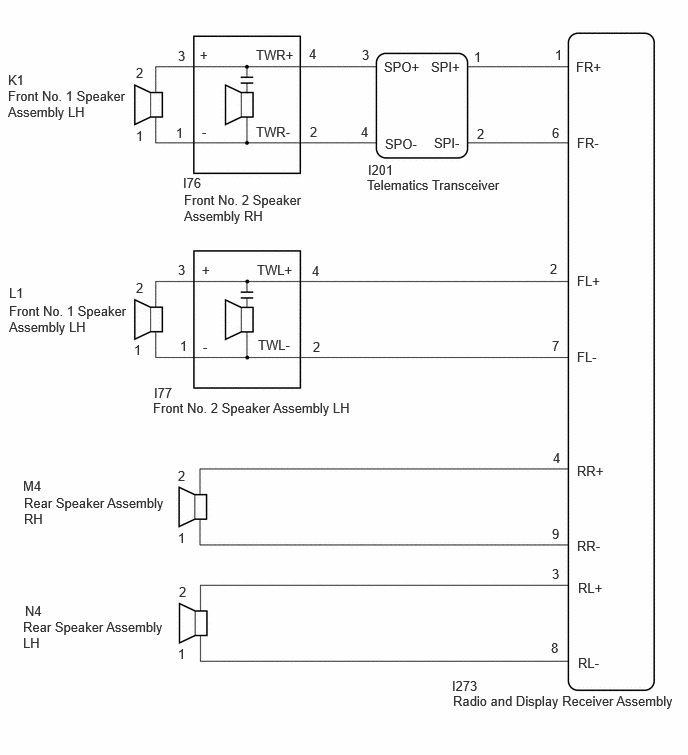
CAUTION / NOTICE / HINT
- NOTICE:
- ·
When replacing the telematics transceiver, make sure to replace it with a new one.
·Depending on the parts that are replaced during vehicle inspection or maintenance, performing initialization, registration or calibration may be needed.
PROCEDURE
Choose the model to be inspected.
- Result:
Result Proceed to for 4 Speakers A for 6 Speakers B
A
B
Pre-procedure1
Disconnect the I273 radio and display receiver assembly connector.
Disconnect the L1 front No. 1 speaker assembly LH connector.
Disconnect the M4 rear speaker assembly RH connector.
Disconnect the N4 rear speaker assembly LH connector.
Disconnect the I201 telematics transceiver connector.
Procedure1
Measure the resistance according to the value(s) in the table below.
- Standard Resistance:
Tester Connection Condition Specified Condition I273-1 (FR+) - Body ground Always 10 kΩ or higher I273-6 (FR-) - Body ground Always 10 kΩ or higher I273-2 (FL+) - Body ground Always 10 kΩ or higher I273-7 (FL-) - Body ground Always 10 kΩ or higher I273-4 (RR+) - Body ground Always 10 kΩ or higher I273-9 (RR-) - Body ground Always 10 kΩ or higher I273-3 (RL+) - Body ground Always 10 kΩ or higher I273-8 (RL-) - Body ground Always 10 kΩ or higher
- Result:
Proceed to OK NG
Post-procedure1
None
OK
NG
Pre-procedure1
Disconnect the K1 front No. 1 speaker assembly RH connector.
Disconnect the I201 telematics transceiver connector.
Procedure1
Measure the resistance according to the value(s) in the table below.
- Standard Resistance:
Tester Connection Condition Specified Condition I201-3 (SPO+) - Body ground Always 10 kΩ or higher I201-4 (SPO-) - Body ground Always 10 kΩ or higher
- Result:
Proceed to OK NG
Post-procedure1
None
OK
NG
- Result:
Proceed to OK NG
OK
NG
- Result:
Proceed to OK NG
OK
NG
Pre-procedure1
Remove the telematics transceiver.
Procedure1
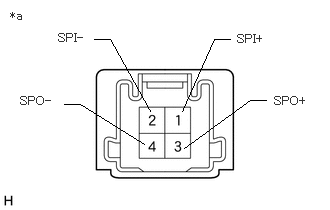
| *a | Component without harness connected
(Telematics Transceiver) |
Measure the resistance according to the value(s) in the table below.
- Standard Resistance:
Tester Connection Condition Specified Condition 1 (SPI+) - 3 (SPO+) Always Below 1 Ω 2 (SPI-) - 4 (SPO-) Always Below 1 Ω 1 (SPI+) - 2 (SPI-) Always 10 kΩ or higher 3 (SPO+) - 4 (SPO-) Always 10 kΩ or higher
- Result:
Proceed to OK NG
Post-procedure1
None
OK
NG
Pre-procedure1
Disconnect the I273 radio and display receiver assembly connector.
Disconnect the I77 front No. 2 speaker assembly LH connector.
Disconnect the M4 rear speaker assembly RH connector.
Disconnect the N4 rear speaker assembly LH connectors.
Disconnect the I201 telematics transceiver connector.
Procedure1
Measure the resistance according to the value(s) in the table below.
- Standard Resistance:
Tester Connection Condition Specified Condition I273-1 (FR+) - Body ground Always 10 kΩ or higher I273-6 (FR-) - Body ground Always 10 kΩ or higher I273-2 (FL+) - Body ground Always 10 kΩ or higher I273-7 (FL-) - Body ground Always 10 kΩ or higher I273-4 (RR+) - Body ground Always 10 kΩ or higher I273-9 (RR-) - Body ground Always 10 kΩ or higher I273-3 (RL+) - Body ground Always 10 kΩ or higher I273-8 (RL-) - Body ground Always 10 kΩ or higher
- Result:
Proceed to OK NG
Post-procedure1
None
OK
NG
Pre-procedure1
Disconnect the I76 front No. 2 speaker assembly RH connector.
Disconnect the I201 telematics transceiver connector.
Procedure1
Measure the resistance according to the value(s) in the table below.
- Standard Resistance:
Tester Connection Condition Specified Condition I201-3 (SPO+) - Body ground Always 10 kΩ or higher I201-4 (SPO-) - Body ground Always 10 kΩ or higher
- Result:
Proceed to OK NG
Post-procedure1
None
OK
NG
Pre-procedure1
Disconnect the K1 front No. 1 speaker assembly RH connector.
Disconnect the L1 front No. 1 speaker assembly LH connector.
Disconnect the I76 front No. 2 speaker assembly RH connector.
Disconnect the I77 front No. 2 speaker assembly LH connector.
Procedure1
Measure the resistance according to the value(s) in the table below.
- Standard Resistance:
Tester Connection Condition Specified Condition K1-2 - Body ground Always 10 kΩ or higher K1-1 - Body ground Always 10 kΩ or higher L1-2 - Body ground Always 10 kΩ or higher L1-1 - Body ground Always 10 kΩ or higher
- Result:
Proceed to OK NG
Post-procedure1
None
OK
NG
- Result:
Proceed to OK NG
OK
NG
- Result:
Proceed to OK NG
OK
NG
- Result:
Proceed to OK NG
OK
NG
Pre-procedure1
Remove the telematics transceiver.
Procedure1
| *a | Component without harness connected
(Telematics Transceiver) |
Measure the resistance according to the value(s) in the table below.
- Standard Resistance:
Tester Connection Condition Specified Condition 1 (SPI+) - 3 (SPO+) Always Below 1 Ω 2 (SPI-) - 4 (SPO-) Always Below 1 Ω 1 (SPI+) - 2 (SPI-) Always 10 kΩ or higher 3 (SPO+) - 4 (SPO-) Always 10 kΩ or higher
- Result:
Proceed to OK NG
Post-procedure1
None
OK
NG