NAVIGATION / MULTI INFO DISPLAY NAVIGATION SYSTEM(Production Date from 2023/04) Radio Wave Reception Failure
CAUTION / NOTICE / HINT
- NOTICE:
-
Depending on the parts that are replaced during vehicle inspection or maintenance, performing initialization, registration or calibration may be needed.
PROCEDURE
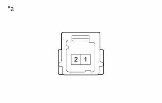
| *a | Front view of wire harness connector
(to Roof Antenna Assembly) |
Prepare for check
Ensure that the connector between the roof antenna assembly and the No. 3 antenna cord sub-assembly is visible.
Disconnect the connector between the roof antenna assembly and the No. 3 antenna cord sub-assembly.
Inspect for noise
With the connector of the radio and display receiver assembly connected, turn the ignition switch to ON.
Turn the audio system on and enter radio mode.
Confirm that noise is output from the speakers when contacting terminal 1 of the No. 3 antenna cord sub-assembly with a screwdriver or metal object such as a thin metal wire.
- OK:
Rasping noise occurs.
Measure voltage
Measure the voltage according to the value(s) in the table below.
- Standard Voltage:
Tester Connection Condition Specified Condition 1 - Body ground Receiving radio broadcast 7 to 16 V
- Result:
Proceed to OK NG
OK
NG
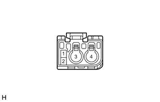
| *a | Front view of wire harness connector
(to No. 3 Antenna Cord Sub-assembly) |
Prepare for check
Ensure that the connector between the No. 3 antenna cord sub-assembly and the No. 2 antenna cord sub-assembly is visible.
Disconnect the connector between the No. 3 antenna cord sub-assembly and the No. 2 antenna cord sub-assembly.
Inspect for noise
With the connector of the radio and display receiver assembly connected, turn the ignition switch to ON.
Turn the audio system on and enter radio mode.
Confirm that noise is output from the speakers when contacting terminal 1 of the No. 2 antenna cord sub-assembly with a screwdriver or metal object such as a thin metal wire.
- OK:
Rasping noise occurs.
Measure voltage
Measure the voltage according to the value(s) in the table below.
- Standard Voltage:
Tester Connection Condition Specified Condition F-1 - Body ground Receiving radio broadcast 7 to 16 V
- Result:
Proceed to OK NG
OK
NG
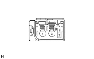
| *a | Front view of wire harness connector
(to No. 2 Antenna Cord Sub-assembly) |
Prepare for check
Ensure that the connector between the No. 2 antenna cord sub-assembly and antenna cord sub-assembly is visible.
Disconnect the connector between the No. 2 antenna cord sub-assembly and antenna cord sub-assembly.
Inspect for Noise
With the connector of the radio and display receiver assembly connected, turn the ignition switch to ON.
Turn the audio system on and enter radio mode.
Confirm that noise is output from the speakers when contacting terminal 1 of the antenna cord sub-assembly with a screwdriver or metal object such as a thin metal wire.
- OK:
Rasping noise occurs
Measure voltage
Measure the voltage according to the value(s) in the table below.
- Standard Voltage:
Tester Connection Condition Specified Condition G-1 - Body ground Receiving radio broadcast 7 to 16 V
- Result:
Proceed to OK NG
OK
NG
Prepare the radio and display receiver assembly for removal.
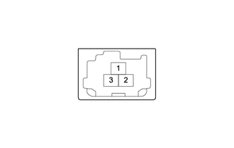
| *a | Component without harness connected
(Radio and Display Receiver Assembly) |
Measure the voltage according to the value(s) in the table below.
- Standard Voltage:
Tester Connection Condition Specified Condition RA-1 (ANT+) - Body ground Receiving radio broadcasts 7 to 16 V
Disconnect the RA radio and display receiver assembly connector.
With all other radio and display receiver assembly connectors connected, turn the ignition switch to ON.
Turn the audio system on and enter radio mode.
Confirm that noise is output from the speakers when contacting terminal 1 of the radio and display receiver assembly with a screwdriver or metal object such as a thin metal wire.
- OK:
Rasping noise occurs.
- Result:
Proceed to OK NG
OK
NG