RM38T0EC _56 Audio / Visual / Telematics _111969 PARK ASSIST / MONITORING _0587004 PANORAMIC VIEW MONITOR SYSTEM(Production Date from 2023/04) C

PARK ASSIST / MONITORING  PANORAMIC VIEW MONITOR SYSTEM(Production Date from 2023/04)  C162287  Rear Camera Image Signal Missing Message  C168187  Front Camera Image Signal Missing Message  C168E87  Side Camera (Left) Image Signal Missing Message  C169D87  Side Camera (Right) Image Signal Missing Message  


DESCRIPTION

This DTC is stored if the parking assist ECU judges as a result of its self check that the signals or signal lines between the parking assist ECU and the rear television camera assembly are not normal.

DTC No. Detection Item DTC Detection Condition Trouble Area DTC Output from Priority
C162287 Rear Camera Image Signal Missing Message Open or short in the rear television camera signal circuit
·

Harness or connector

·

Rear television camera assembly

·

Parking assist ECU


Circumference Monitoring Camera Control Module A
C168187 Front Camera Image Signal Missing Message Front television camera power supply failure
·

Harness or connector

·

Front television camera assembly

·

Parking assist ECU


Circumference Monitoring Camera Control Module A
C168E87 Side Camera (Left) Image Signal Missing Message Side camera feedback malfunction (Left)
·

Harness or connector

·

Parking assist ECU

·

Side television camera assembly LH

·

Outer rear view mirror assembly LH


Circumference Monitoring Camera Control Module A
C169D87 Side Camera (Right) Image Signal Missing Message Side camera feedback malfunction (Right)
·

Harness or connector

·

Parking assist ECU

·

Side television camera assembly RH

·

Outer rear view mirror assembly RH


Circumference Monitoring Camera Control Module A

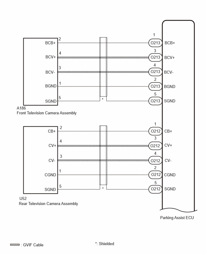
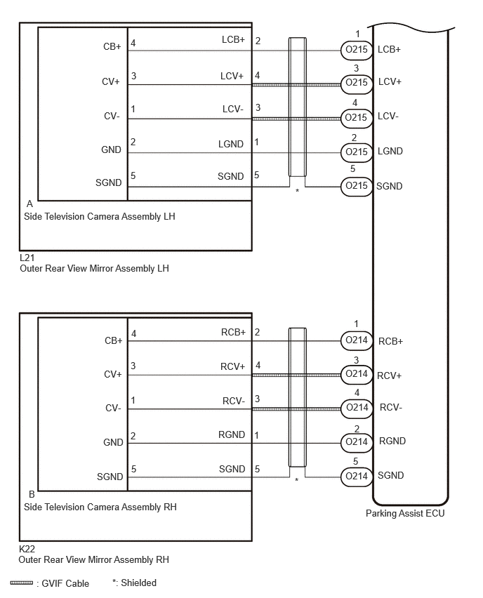
WIRING DIAGRAM

E517090E05
0.583,3.844 2.792,4.021 2.208,0.177 10 false Front Television Camera Assembly 0.729,8.438 2.563,8.635 1.833,0.198 10 false : GVIF Cable 1.573,1.406 1.969,1.573 0.396,0.167 10 false BCB+ 1.583,1.896 1.979,2.063 0.396,0.167 10 false BCV+ 1.583,2.427 1.979,2.594 0.396,0.167 10 false BCV- 1.573,2.906 2.021,3.063 0.448,0.156 10 false BGND 1.573,3.438 2.021,3.594 0.448,0.156 10 false SGND 2.042,3.313 2.49,3.469 0.448,0.156 10 false 5 2.052,2.813 2.313,2.969 0.26,0.156 10 false 1 2.042,2.271 2.49,2.427 0.448,0.156 10 false 3 2.052,1.76 2.5,1.917 0.448,0.156 10 false 4 2.042,1.271 2.49,1.427 0.448,0.156 10 false 2 0.583,3.677 1.042,3.896 0.458,0.219 10 false A186 3.542,3.385 3.99,3.542 0.448,0.156 10 false * 5.573,7.49 6.948,7.667 1.375,0.177 10 false Parking Assist ECU 5.24,1.406 5.635,1.573 0.396,0.167 10 false O213 5.729,1.406 6.125,1.573 0.396,0.167 10 false BCB+ 5.719,1.917 6.115,2.083 0.396,0.167 10 false BCV+ 5.708,2.427 6.104,2.594 0.396,0.167 10 false BCV- 5.708,2.927 6.156,3.083 0.448,0.156 10 false BGND 5.708,3.427 6.156,3.583 0.448,0.156 10 false SGND 5.323,1.125 5.646,1.333 0.323,0.208 10 false 1 5.354,1.677 5.802,1.833 0.448,0.156 10 false 3 5.344,2.177 5.792,2.333 0.448,0.156 10 false 4 5.365,2.677 5.813,2.833 0.448,0.156 10 false 2 5.365,3.188 5.813,3.344 0.448,0.156 10 false 5 3.313,8.396 5.146,8.594 1.833,0.198 10 false *: Shielded 0.656,7 2.865,7.177 2.208,0.177 10 false Rear Television Camera Assembly 0.677,6.823 1.135,7.042 0.458,0.219 10 false U52 1.667,4.479 2.063,4.646 0.396,0.167 10 false CB+ 1.688,4.979 2.083,5.146 0.396,0.167 10 false CV+ 1.688,5.5 2.083,5.667 0.396,0.167 10 false CV- 1.552,6 2,6.156 0.448,0.156 10 false CGND 1.552,6.51 2,6.667 0.448,0.156 10 false SGND 2.083,4.354 2.531,4.51 0.448,0.156 10 false 2 2.073,4.823 2.521,4.979 0.448,0.156 10 false 4 2.083,5.354 2.531,5.51 0.448,0.156 10 false 3 2.052,5.865 2.313,6.021 0.26,0.156 10 false 1 2.063,6.396 2.51,6.552 0.448,0.156 10 false 5 3.552,6.49 4,6.646 0.448,0.156 10 false * 5.719,4.479 6.115,4.646 0.396,0.167 10 false CB+ 5.719,4.969 6.115,5.135 0.396,0.167 10 false CV+ 5.729,5.5 6.125,5.667 0.396,0.167 10 false CV- 5.708,6 6.156,6.156 0.448,0.156 10 false CGND 5.719,6.49 6.167,6.646 0.448,0.156 10 false SGND 5.25,4.479 5.646,4.646 0.396,0.167 10 false O212 5.365,4.229 5.688,4.438 0.323,0.208 10 false 1 5.365,4.719 5.813,4.875 0.448,0.156 10 false 3 5.365,5.25 5.813,5.406 0.448,0.156 10 false 4 5.365,5.75 5.813,5.906 0.448,0.156 10 false 2 5.375,6.271 5.823,6.427 0.448,0.156 10 false 5 5.229,4.99 5.625,5.156 0.396,0.167 10 false O212 5.24,5.51 5.635,5.677 0.396,0.167 10 false O212 5.26,5.99 5.656,6.156 0.396,0.167 10 false O212 5.25,6.49 5.646,6.656 0.396,0.167 10 false O212 5.24,1.906 5.635,2.073 0.396,0.167 10 false O213 5.24,2.406 5.635,2.573 0.396,0.167 10 false O213 5.24,2.917 5.635,3.083 0.396,0.167 10 false O213 5.24,3.427 5.635,3.594 0.396,0.167 10 false O213

E492154E07
5.219,1.958 5.375,2.135 0.156,0.177 10 false 2 5.229,1.438 5.396,1.625 0.167,0.188 10 false 4 5.25,0.927 5.396,1.115 0.146,0.188 10 false 3 5.271,0.417 5.531,0.604 0.26,0.188 10 false 1 5.198,2.417 5.458,2.604 0.26,0.188 10 false 5 3.792,0.521 4.052,0.708 0.26,0.188 10 false 2 3.781,1.031 4.042,1.219 0.26,0.188 10 false 4 3.792,1.51 4.052,1.698 0.26,0.188 10 false 3 3.771,2.021 4.031,2.208 0.26,0.188 10 false 1 3.771,2.51 4.031,2.698 0.26,0.188 10 false 5 1.938,2.021 2.198,2.208 0.26,0.188 10 false 2 1.938,1.531 2.198,1.719 0.26,0.188 10 false 1 1.948,1.042 2.208,1.229 0.26,0.188 10 false 3 1.938,0.552 2.198,0.74 0.26,0.188 10 false 4 1.938,2.521 2.198,2.708 0.26,0.188 10 false 5 1.531,0.604 1.958,0.823 0.427,0.219 10 false CB+ 1.542,1.635 1.927,1.833 0.385,0.198 10 false CV- 1.51,1.125 1.938,1.333 0.427,0.208 10 false CV+ 1.5,2.135 1.969,2.344 0.469,0.208 10 false GND 1.417,2.625 1.896,2.823 0.479,0.198 10 false SGND 5.604,0.646 6,0.823 0.396,0.177 10 false LCB+ 5.615,1.125 6.021,1.344 0.406,0.219 10 false LCV+ 5.604,1.635 6.01,1.833 0.406,0.198 10 false LCV- 5.604,2.156 6.052,2.365 0.448,0.208 10 false LGND 5.583,2.677 6.052,2.865 0.469,0.188 10 false SGND 3.292,0.5 3.698,0.698 0.406,0.198 10 false LCB+ 3.271,1.042 3.688,1.25 0.417,0.208 10 false LCV+ 3.302,1.531 3.698,1.74 0.396,0.208 10 false LCV- 3.24,2.052 3.698,2.24 0.458,0.188 10 false LGND 3.229,2.531 3.677,2.74 0.448,0.208 10 false SGND 0.396,2.938 0.573,3.135 0.177,0.198 10 false A 0.354,3.125 2.99,3.396 2.635,0.271 10 false Side Television Camera Assembly LH 0.281,8.063 0.615,8.24 0.333,0.177 10 false K22 0.292,3.896 2.615,4.125 2.323,0.229 10 false Outer Rear View Mirror Assembly LH 0.271,8.219 2.604,8.406 2.333,0.188 10 false Outer Rear View Mirror Assembly RH 0.427,7.25 0.635,7.438 0.208,0.188 10 false B 0.354,7.438 2.833,7.792 2.479,0.354 10 false Side Television Camera Assembly RH 0.292,3.74 0.625,3.917 0.333,0.177 10 false L21 3.781,6.875 3.948,7.063 0.167,0.188 10 false 5 3.771,6.375 3.958,6.542 0.188,0.167 10 false 1 3.781,5.833 3.969,6 0.188,0.167 10 false 3 3.792,5.333 3.958,5.521 0.167,0.188 10 false 4 3.781,4.844 3.948,5.031 0.167,0.188 10 false 2 5.26,6.281 5.448,6.469 0.188,0.188 10 false 2 5.26,5.74 5.427,5.927 0.167,0.188 10 false 4 5.25,5.26 5.406,5.448 0.156,0.188 10 false 3 5.25,4.719 5.406,4.927 0.156,0.208 10 false 1 5.24,6.76 5.417,6.948 0.177,0.188 10 false 5 1.938,6.385 2.198,6.573 0.26,0.188 10 false 2 1.938,5.854 2.104,6.031 0.167,0.177 10 false 1 1.938,5.344 2.115,5.531 0.177,0.188 10 false 3 1.948,4.865 2.208,5.052 0.26,0.188 10 false 4 1.948,6.875 2.115,7.063 0.167,0.188 10 false 5 1.552,4.969 1.99,5.156 0.438,0.188 10 false CB+ 1.542,5.469 1.99,5.677 0.448,0.208 10 false CV+ 1.563,5.969 1.969,6.188 0.406,0.219 10 false CV- 1.531,6.479 1.979,6.677 0.448,0.198 10 false GND 1.438,6.99 1.875,7.198 0.438,0.208 10 false SGND 3.281,4.844 3.708,5.031 0.427,0.188 10 false RCB+ 3.271,5.354 3.698,5.542 0.427,0.188 10 false RCV+ 3.302,5.865 3.719,6.073 0.417,0.208 10 false RCV- 3.24,6.365 3.708,6.573 0.469,0.208 10 false RGND 3.25,6.875 3.698,7.073 0.448,0.198 10 false SGND 5.615,4.979 6.052,5.177 0.438,0.198 10 false RCB+ 5.594,5.49 6.031,5.677 0.438,0.188 10 false RCV+ 5.635,5.958 6.021,6.146 0.385,0.188 10 false RCV- 5.625,6.458 6.115,6.635 0.49,0.177 10 false RGND 5.604,6.969 6.042,7.156 0.438,0.188 10 false SGND 1.667,8.563 4.135,8.802 2.469,0.24 10 false *: Shielded 5.427,7.531 6.729,7.74 1.302,0.208 10 false Parking Assist ECU 4.385,2.771 4.521,2.927 0.135,0.156 10 false * 4.375,7.063 4.542,7.24 0.167,0.177 10 false * 5.125,0.646 5.51,0.854 0.385,0.208 10 false O215 5.125,1.135 5.51,1.344 0.385,0.208 10 false O215 5.115,1.656 5.5,1.865 0.385,0.208 10 false O215 5.125,2.167 5.51,2.375 0.385,0.208 10 false O215 5.125,2.667 5.51,2.875 0.385,0.208 10 false O215 5.125,4.958 5.51,5.167 0.385,0.208 10 false O214 5.125,5.458 5.51,5.667 0.385,0.208 10 false O214 5.135,5.958 5.573,6.198 0.438,0.24 10 false O214 5.125,6.469 5.51,6.677 0.385,0.208 10 false O214 5.125,6.979 5.51,7.188 0.385,0.208 10 false O214 0.542,8.573 2.375,8.771 1.833,0.198 10 false : GVIF Cable

CAUTION / NOTICE / HINT

NOTICE:

Depending on the parts that are replaced or operations that are performed during vehicle inspection or maintenance, calibration of other systems as well as the panoramic view monitor system may be needed.

Click hereAudio / Visual / Telematics>PARK ASSIST / MONITORING>PANORAMIC VIEW MONITOR SYSTEM (Production Date from 2023/04)>CALIBRATION


PROCEDURE

1.CHECK FOR DTCs
a.

Turn the ignition switch to ON.


b.

Using the GTS, check for DTCs and proceed to the respective link below.

Chassis > Circumference Monitoring Camera Control Module > Trouble Codes
50001 470

Result:
Result Proceed to
Only DTC C162287 is output A
Only DTC C168187 is output B
Only DTC C168E87 is output C
Only DTC C169D87 is output D
Other than above E


A

2.CHECK HARNESS AND CONNECTOR (PARKING ASSIST ECU - REAR TELEVISION CAMERA ASSEMBLY)

B

5.CHECK HARNESS AND CONNECTOR (PARKING ASSIST ECU - FRONT TELEVISION CAMERA ASSEMBLY)

C

8.CHECK HARNESS AND CONNECTOR (PARKING ASSIST ECU - OUTER REAR VIEW MIRROR ASSEMBLY LH)

D

15.CHECK HARNESS AND CONNECTOR (PARKING ASSIST ECU - OUTER REAR VIEW MIRROR ASSEMBLY RH)

E

22.CHECK FOR DTCs
2.CHECK HARNESS AND CONNECTOR (PARKING ASSIST ECU - REAR TELEVISION CAMERA ASSEMBLY)
a.

Disconnect the O212 parking assist ECU connector.


b.

Disconnect the U52 rear television camera assembly connector.


c.

Measure the resistance according to the value(s) in the table below.

Standard Resistance:
Tester Connection Condition Specified Condition
O212-1 (CB+) - U52-2 (CB+) Always Below 1 Ω
O212-3 (CV+) - U52-4 (CV+) Always Below 1 Ω
O212-4 (CV-) - U52-3 (CV-) Always Below 1 Ω
O212-2 (CGND) - U52-1 (CGND) Always Below 1 Ω
O212-5 (SGND) - U52-5 (SGND) Always Below 1 Ω
O212-1 (CB+) or U52-2 (CB+) - Body ground Always 10 kΩ or higher
O212-3 (CV+) or U52-4 (CV+) - Body ground Always 10 kΩ or higher
O212-4 (CV-) or U52-3 (CV-) - Body ground Always 10 kΩ or higher
O212-2 (CGND) or U52-1 (CGND) - Body ground Always 10 kΩ or higher
O212-5 (SGND) or U52-5 (SGND) - Body ground Always 10 kΩ or higher


Result:
Proceed to
OK
NG


OK

3.CHECK PARKING ASSIST ECU (CV+, CV-)

NG

REPAIR OR REPLACE HARNESS OR CONNECTOR

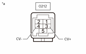
3.CHECK PARKING ASSIST ECU (CV+, CV-)
a.
E547637C01
1.427,0.104 2.01,0.406 0.583,0.302 0.917,1.583 1.083,1.583 1.083,1.583 1.458,1.083 true 2.521,1.583 2.354,1.583 2.354,1.583 1.979,1.083 true 0.073,0.063 0.385,0.26 0.313,0.198 10 false *a 0.646,1.49 1.167,1.688 0.521,0.198 10 false CV- 2.573,1.5 3.094,1.698 0.521,0.198 10 false CV+ 1.542,0.167 2.156,0.365 0.615,0.198 10 false O212
*a Component without harness connected
(Parking Assist ECU)


Disconnect the O212 parking assist ECU connector.


b.

Measure the resistance according to the value(s) in the table below.

Standard Resistance:
Tester Connection Condition Specified Condition
O212-3 (CV+) - Body ground Always 10 kΩ or higher
O212-4 (CV-) - Body ground Always 10 kΩ or higher


Result:
Proceed to
OK
NG


OK

4.CHECK PARKING ASSIST ECU (CB+, CGND)

NG

4.CHECK PARKING ASSIST ECU (CB+, CGND)
a.

Disconnect the U52 rear television camera assembly.


b.

Measure the resistance according to the value(s) in the table below.

Standard Resistance:
Tester Connection Condition Specified Condition
U52-1 (CGND) - Body ground Always Below 1 Ω


c.

Measure the voltage according to the value(s) in the table below.

Standard Voltage:
Tester Connection Switch Condition Specified Condition
U52-2 (CB+) - U52-1 (CGND) Ignition switch ON 7.5 to 8.5 V


Result:
Proceed to
OK
NG


OK

NG

5.CHECK HARNESS AND CONNECTOR (PARKING ASSIST ECU - FRONT TELEVISION CAMERA ASSEMBLY)
a.

Disconnect the O213 parking assist ECU connector.


b.

Disconnect the A186 front television camera assembly connector.


c.

Measure the resistance according to the value(s) in the table below.

Standard Resistance:
Tester Connection Condition Specified Condition
O213-1 (BCB+) - A186-2 (BCB+) Always Below 1 Ω
O213-3 (BCV+) - A186-4 (BCV+) Always Below 1 Ω
O213-4 (BCV-) - A186-3 (BCV-) Always Below 1 Ω
O213-2 (BGND) - A186-1 (BGND) Always Below 1 Ω
O213-5 (SGND) - A186-5 (SGND) Always Below 1 Ω
O213-1 (BCB+) or A186-2 (BCB+) - Body ground Always 10 kΩ or higher
O213-3 (BCV+) or A186-4 (BCV+) - Body ground Always 10 kΩ or higher
O213-4 (BCV-) or A186-3 (BCV-) - Body ground Always 10 kΩ or higher
O213-2 (BGND) or A186-1 (BGND) - Body ground Always 10 kΩ or higher
O213-5 (SGND) or A186-5 (SGND) - Body ground Always 10 kΩ or higher


Result:
Proceed to
OK
NG


OK

6.CHECK PARKING ASSIST ECU (BCV+, BCV-)

NG

REPAIR OR REPLACE HARNESS OR CONNECTOR

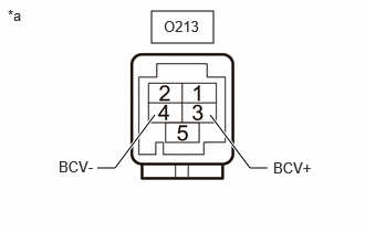
6.CHECK PARKING ASSIST ECU (BCV+, BCV-)
a.
E547637C04
1.427,0.104 2.01,0.406 0.583,0.302 0.917,1.583 1.083,1.583 1.083,1.583 1.458,1.083 true 2.521,1.583 2.354,1.583 2.354,1.583 1.979,1.083 true 0.073,0.063 0.385,0.26 0.313,0.198 10 false *a 0.552,1.49 1.073,1.688 0.521,0.198 10 false BCV- 2.573,1.5 3.094,1.698 0.521,0.198 10 false BCV+ 1.542,0.167 2.156,0.365 0.615,0.198 10 false O213
*a Component without harness connected
(Parking Assist ECU)


Disconnect the O213 parking assist ECU connector.


b.

Measure the resistance according to the value(s) in the table below.

Standard Resistance:
Tester Connection Condition Specified Condition
O213-3 (BCV+) - Body ground Always 10 kΩ or higher
O213-4 (BCV-) - Body ground Always 10 kΩ or higher


Result:
Proceed to
OK
NG


OK

7.CHECK PARKING ASSIST ECU (BCB+, BGND)

NG

7.CHECK PARKING ASSIST ECU (BCB+, BGND)
a.

Disconnect the A186 front television camera assembly connector.


b.

Measure the resistance according to the value(s) in the table below.

Standard Resistance:
Tester Connection Condition Specified Condition
A186-1 (BGND) - Body ground Always Below 1 Ω


c.

Measure the voltage according to the value(s) in the table below.

Standard Voltage:
Tester Connection Switch Condition Specified Condition
A186-2 (BCB+) - A186-1 (BGND) Ignition switch ON 7.5 to 8.5 V


Result:
Proceed to
OK
NG


OK

NG

8.CHECK HARNESS AND CONNECTOR (PARKING ASSIST ECU - OUTER REAR VIEW MIRROR ASSEMBLY LH)
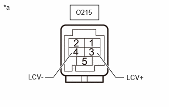
a.

Disconnect the O215 parking assist ECU connector.


b.

Disconnect the L21 outer rear view mirror assembly LH connector.


c.

Measure the resistance according to the value(s) in the table below.

Standard Resistance:
Tester Connection Condition Specified Condition
O215-1 (LCB+) - L21-2 (LCB+) Always Below 1 Ω
O215-3 (LCV+) - L21-4 (LCV+) Always Below 1 Ω
O215-4 (LCV-) - L21-3 (LCV-) Always Below 1 Ω
O215-2 (LGND) - L21-1 (LGND) Always Below 1 Ω
O215-5 (SGND) - L21-5 (SGND) Always Below 1 Ω
O215-1 (LCB+) or L21-2 (LCB+) - Body ground Always 10 kΩ or higher
O215-3 (LCV+) or L21-4 (LCV+) - Body ground Always 10 kΩ or higher
O215-4 (LCV-) or L21-3 (LCV-) - Body ground Always 10 kΩ or higher
O215-2 (LGND) or L21-1 (LGND) - Body ground Always 10 kΩ or higher
O215-5 (SGND) or L21-5 (SGND) - Body ground Always 10 kΩ or higher


Result:
Proceed to
OK
NG


OK

9.CHECK PARKING ASSIST ECU (LCV+, LCV-)

NG

REPAIR OR REPLACE HARNESS OR CONNECTOR

9.CHECK PARKING ASSIST ECU (LCV+, LCV-)
a.
E547637C05
1.427,0.104 2.01,0.406 0.583,0.302 0.917,1.583 1.083,1.583 1.083,1.583 1.458,1.083 true 2.521,1.583 2.354,1.583 2.354,1.583 1.979,1.083 true 0.073,0.063 0.385,0.26 0.313,0.198 10 false *a 0.573,1.49 1.094,1.688 0.521,0.198 10 false LCV- 2.573,1.5 3.094,1.698 0.521,0.198 10 false LCV+ 1.542,0.167 2.156,0.365 0.615,0.198 10 false O215
*a Component without harness connected
(Parking Assist ECU)


Disconnect the O215 parking assist ECU connector.


b.

Measure the resistance according to the value(s) in the table below.

Standard Resistance:
Tester Connection Condition Specified Condition
O215-3 (LCV+) - Body ground Always 10 kΩ or higher
O215-4 (LCV-) - Body ground Always 10 kΩ or higher


Result:
Proceed to
OK
NG


OK

10.CHECK PARKING ASSIST ECU (LCB+, LGND)

NG

10.CHECK PARKING ASSIST ECU (LCB+, LGND)
a.

Disconnect the L21 outer rear view mirror assembly LH connector.


b.

Measure the resistance according to the value(s) in the table below.

Standard Resistance:
Tester Connection Condition Specified Condition
L21-1 (LGND) - Body ground Always Below 1 Ω


c.

Measure the voltage according to the value(s) in the table below.

Standard Voltage:
Tester Connection Switch Condition Specified Condition
L21-2 (LCB+) - L21-1 (LGND) Ignition switch ON 7.5 to 8.5 V


Result:
Proceed to
OK
NG


OK

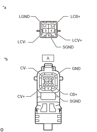
11.INSPECT OUTER REAR VIEW MIRROR ASSEMBLY LH

NG

11.INSPECT OUTER REAR VIEW MIRROR ASSEMBLY LH
a.
E434382C95
1.5,1.948 1.906,2.177 0.406,0.229 0.917,3.417 1.083,3.417 1.083,3.417 1.625,2.99 true 2.417,3.583 2.25,3.583 2.25,3.583 1.771,3.167 true 2.417,3.333 2.25,3.333 2.25,3.333 1.802,2.99 true 2.5,2.417 2.333,2.417 2.333,2.417 1.802,2.802 true 1,2.417 1.167,2.417 1.167,2.417 1.615,2.792 true 2.167,1.667 2,1.667 2,1.667 1.75,1.25 true 2.5,1.417 2.333,1.417 2.333,1.417 1.896,1.125 true 2.417,0.583 2.25,0.583 2.25,0.583 1.854,0.969 true 1.083,0.583 1.25,0.583 1.25,0.583 1.594,0.969 true 1,1.5 1.167,1.5 1.167,1.5 1.552,1.135 true 0.094,0.177 0.406,0.375 0.313,0.198 10 false *a 0.146,2.01 0.458,2.208 0.313,0.198 10 false *b 2.5,0.5 3.115,0.698 0.615,0.198 10 false LCB+ 0.625,1.396 1.24,1.594 0.615,0.198 10 false LCV- 2.563,1.344 3.177,1.542 0.615,0.198 10 false LCV+ 0.677,0.5 1.292,0.698 0.615,0.198 10 false LGND 2.219,1.583 2.833,1.781 0.615,0.198 10 false SGND 0.615,3.333 1.229,3.531 0.615,0.198 10 false CV+ 2.469,3.26 3.083,3.458 0.615,0.198 10 false CB+ 2.552,2.344 3.167,2.542 0.615,0.198 10 false GND 0.719,2.323 1.333,2.521 0.615,0.198 10 false CV- 2.469,3.5 3.083,3.698 0.615,0.198 10 false SGND 1.656,1.979 1.906,2.177 0.25,0.198 10 false A
*a Component without harness connected
(Outer Rear View Mirror Assembly LH)
*b Front view of wire harness connector
(to Side Television Camera Assembly LH)


Disconnect the outer rear view mirror assembly LH connector.


b.

Disconnect the side television camera assembly LH connector.


c.

Measure the resistance according to the value(s) in the table below.

Standard Resistance:
Tester Connection Condition Specified Condition
2 (LCB+) - A-4 (CB+) Always Below 1 Ω
4 (LCV+) - A-3 (CV+) Always Below 1 Ω
3 (LCV-) - A-1 (CV-) Always Below 1 Ω
1 (LGND) - A-2 (GND) Always Below 1 Ω
5 (SGND) - A-5 (SGND) Always Below 1 Ω
2 (LCB+) or A-4 (CB+) - Body ground Always 10 kΩ or higher
4 (LCV+) or A-3 (CV+) - Body ground Always 10 kΩ or higher
3 (LCV-) or A-1 (CV-) - Body ground Always 10 kΩ or higher
1 (LGND) or A-2 (GND) - Body ground Always 10 kΩ or higher
5 (SGND) or A-5 (SGND) - Body ground Always 10 kΩ or higher


Result:
Proceed to
OK
NG


OK

12.REPLACE SIDE TELEVISION CAMERA ASSEMBLY LH

NG

13.CLEAR DTC
a.

Clear the DTCs.

Chassis > Circumference Monitoring Camera Control Module > Clear DTCs
50002 470

Result:
Proceed to
NEXT


NEXT

14.CHECK FOR DTC
14.CHECK FOR DTC
a.

Check for DTCs.

Chassis > Circumference Monitoring Camera Control Module > Trouble Codes
50001 470

Result:
Result Proceed to
C168E87 is not output A
C168E87 is output B


A

END (SIDE TELEVISION CAMERA ASSEMBLY LH WAS DEFECTIVE)

B

15.CHECK HARNESS AND CONNECTOR (PARKING ASSIST ECU - OUTER REAR VIEW MIRROR ASSEMBLY RH)
a.

Disconnect the O214 parking assist ECU connector.


b.

Disconnect the K22 outer rear view mirror assembly RH connector.


c.

Measure the resistance according to the value(s) in the table below.

Standard Resistance:
Tester Connection Condition Specified Condition
O214-1 (RCB+) - K22-2 (RCB+) Always Below 1 Ω
O214-3 (RCV+) - K22-4 (RCV+) Always Below 1 Ω
O214-4 (RCV-) - K22-3 (RCV-) Always Below 1 Ω
O214-2 (RGND) - K22-1 (RGND) Always Below 1 Ω
O214-5 (SGND) - K22-5 (SGND) Always Below 1 Ω
O214-1 (RCB+) or K22-2 (RCB+) - Body ground Always 10 kΩ or higher
O214-3 (RCV+) or K22-4 (RCV+) - Body ground Always 10 kΩ or higher
O214-4 (RCV-) or K22-3 (RCV-) - Body ground Always 10 kΩ or higher
O214-2 (RGND) or K22-1 (RGND) - Body ground Always 10 kΩ or higher
O214-5 (SGND) or K22-5 (SGND) - Body ground Always 10 kΩ or higher


Result:
Proceed to
OK
NG


OK

16.CHECK PARKING ASSIST ECU (RCV+, RCV-)

NG

REPAIR OR REPLACE HARNESS OR CONNECTOR

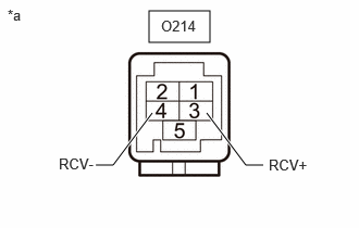
16.CHECK PARKING ASSIST ECU (RCV+, RCV-)
a.
E547637C06
1.427,0.104 2.01,0.406 0.583,0.302 0.917,1.583 1.083,1.583 1.083,1.583 1.458,1.083 true 2.521,1.583 2.354,1.583 2.354,1.583 1.979,1.083 true 0.073,0.063 0.385,0.26 0.313,0.198 10 false *a 0.563,1.49 1.083,1.688 0.521,0.198 10 false RCV- 2.573,1.5 3.094,1.698 0.521,0.198 10 false RCV+ 1.542,0.167 2.156,0.365 0.615,0.198 10 false O214
*a Component without harness connected
(Parking Assist ECU)


Disconnect the O214 parking assist ECU connector.


b.

Measure the resistance according to the value(s) in the table below.

Standard Resistance:
Tester Connection Condition Specified Condition
O214-3 (RCV+) - Body ground Always 10 kΩ or higher
O214-4 (RCV-) - Body ground Always 10 kΩ or higher


Result:
Proceed to
OK
NG


OK

17.CHECK PARKING ASSIST ECU (RCB+, RGND)

NG

17.CHECK PARKING ASSIST ECU (RCB+, RGND)
a.

Disconnect the K22 outer rear view mirror assembly RH connector.


b.

Measure the resistance according to the value(s) in the table below.

Standard Resistance:
Tester Connection Condition Specified Condition
K22-1 (RGND) - Body ground Always Below 1 Ω


c.

Measure the voltage according to the value(s) in the table below.

Standard Voltage:
Tester Connection Switch Condition Specified Condition
K22-2 (RCB+) - K22-1 (RGND) Ignition switch ON 7.5 to 8.5 V


Result:
Proceed to
OK
NG


OK

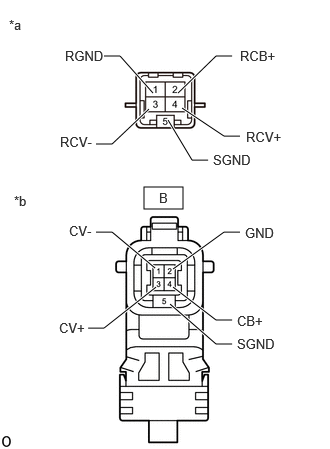
18.INSPECT OUTER REAR VIEW MIRROR ASSEMBLY RH

NG

18.INSPECT OUTER REAR VIEW MIRROR ASSEMBLY RH
a.
E434382C96
1.5,1.948 1.906,2.177 0.406,0.229 0.917,3.417 1.083,3.417 1.083,3.417 1.625,2.99 true 2.417,3.583 2.25,3.583 2.25,3.583 1.771,3.167 true 2.417,3.333 2.25,3.333 2.25,3.333 1.802,2.99 true 2.5,2.417 2.333,2.417 2.333,2.417 1.802,2.802 true 1,2.417 1.167,2.417 1.167,2.417 1.615,2.792 true 2.167,1.667 2,1.667 2,1.667 1.75,1.25 true 2.5,1.417 2.333,1.417 2.333,1.417 1.896,1.125 true 2.417,0.583 2.25,0.583 2.25,0.583 1.854,0.969 true 1.083,0.583 1.25,0.583 1.25,0.583 1.594,0.969 true 1,1.5 1.167,1.5 1.167,1.5 1.552,1.135 true 0.094,0.177 0.406,0.375 0.313,0.198 10 false *a 0.146,2.01 0.458,2.208 0.313,0.198 10 false *b 2.5,0.5 3.115,0.698 0.615,0.198 10 false RCB+ 0.625,1.396 1.24,1.594 0.615,0.198 10 false RCV- 2.563,1.344 3.177,1.542 0.615,0.198 10 false RCV+ 0.677,0.5 1.292,0.698 0.615,0.198 10 false RGND 2.219,1.583 2.833,1.781 0.615,0.198 10 false SGND 0.615,3.333 1.229,3.531 0.615,0.198 10 false CV+ 2.469,3.26 3.083,3.458 0.615,0.198 10 false CB+ 2.552,2.344 3.167,2.542 0.615,0.198 10 false GND 0.719,2.323 1.333,2.521 0.615,0.198 10 false CV- 2.469,3.5 3.083,3.698 0.615,0.198 10 false SGND 1.656,1.979 1.906,2.177 0.25,0.198 10 false B
*a Component without harness connected
(Outer Rear View Mirror Assembly RH)
*b Front view of wire harness connector
(to Side Television Camera Assembly RH)


Disconnect the side television camera assembly RH connector.


b.

Disconnect the outer rear view mirror assembly RH connector.


c.

Measure the resistance according to the value(s) in the table below.

Standard Resistance:
Tester Connection Condition Specified Condition
2 (RCB+) - B-4 (CB+) Always Below 1 Ω
4 (RCV+) - B-3 (CV+) Always Below 1 Ω
3 (RCV-) - B-1 (CV-) Always Below 1 Ω
1 (RGND) - B-2 (GND) Always Below 1 Ω
5 (SGND) - B-5 (SGND) Always 10 kΩ or higher
2 (RCB+) or B-4 (RCB+) - Body ground Always 10 kΩ or higher
4 (RCV+) or B-3 (CV+) - Body ground Always 10 kΩ or higher
3 (RCV-) or B-1 (CV-) - Body ground Always 10 kΩ or higher
1 (RGND) or B-2 (GND) - Body ground Always 10 kΩ or higher
5 (SGND) or B-5 (SGND) - Body ground Always 10 kΩ or higher


Result:
Proceed to
OK
NG


OK

19.REPLACE SIDE TELEVISION CAMERA ASSEMBLY RH

NG

20.CLEAR DTC
a.

Clear the DTCs.

Chassis > Circumference Monitoring Camera Control Module > Clear DTCs
50002 470

Result:
Proceed to
NEXT


NEXT

21.CHECK FOR DTC
21.CHECK FOR DTC
a.

Check for DTCs.

Chassis > Circumference Monitoring Camera Control Module > Trouble Codes
50001 470

Result:
Result Proceed to
C169D87 is not output A
C169D87 is output B


A

END (SIDE TELEVISION CAMERA ASSEMBLY RH WAS DEFECTIVE)

B

22.CHECK FOR DTCs
a.

Disconnect the O212 parking assist ECU connector.


b.

Using the GTS, check for DTCs and proceed to the respective link below.

Chassis > Circumference Monitoring Camera Control Module > Trouble Codes
50001 470

Result:
Result Proceed to
Only DTC C162287 is output A
DTC C162287 is output together with either C168187, C168E87, or C169D87 B


A

2.CHECK HARNESS AND CONNECTOR (PARKING ASSIST ECU - REAR TELEVISION CAMERA ASSEMBLY)

B

23.CHECK FOR DTCs
23.CHECK FOR DTCs
a.

Connect the O212 parking assist ECU connector.


b.

Disconnect the O213 parking assist ECU connector.


c.

Using the GTS, check for DTCs and proceed to the respective link below.

Chassis > Circumference Monitoring Camera Control Module > Trouble Codes
50001 470

Result:
Result Proceed to
Only DTC C168187 is output A
DTC C168187 is output together with either C162287, C168E87, or C169D87 B


A

5.CHECK HARNESS AND CONNECTOR (PARKING ASSIST ECU - FRONT TELEVISION CAMERA ASSEMBLY)

B

24.CHECK FOR DTCs
24.CHECK FOR DTCs
a.

Connect the O213 parking assist ECU connector.


b.

Disconnect the O215 parking assist ECU connector.


c.

Using the GTS, check for DTCs and proceed to the respective link below.

Chassis > Circumference Monitoring Camera Control Module > Trouble Codes
50001 470

Result:
Result Proceed to
Only DTC C168E87 is output A
DTC C168E87 is output together with either C162287, C168187, or C169D87 B


A

8.CHECK HARNESS AND CONNECTOR (PARKING ASSIST ECU - OUTER REAR VIEW MIRROR ASSEMBLY LH)

B

25.CHECK FOR DTCs
25.CHECK FOR DTCs
a.

Connect the O215 parking assist ECU connector.


b.

Disconnect the O214 parking assist ECU connector.


c.

Using the GTS, check for DTCs and proceed to the respective link below.

Chassis > Circumference Monitoring Camera Control Module > Trouble Codes
50001 470

Result:
Result Proceed to
Only DTC C169D87 is output A
DTC C169D87 is output together with either C162287, C168187, or C168E87 B


A

15.CHECK HARNESS AND CONNECTOR (PARKING ASSIST ECU - OUTER REAR VIEW MIRROR ASSEMBLY RH)

B