PARK ASSIST / MONITORING PARKING ASSIST MONITOR SYSTEM Image from Camera for Parking Assist Monitor is Abnormal
DESCRIPTION
The display signal from the rear television camera assembly is transmitted to the display.
WIRING DIAGRAM
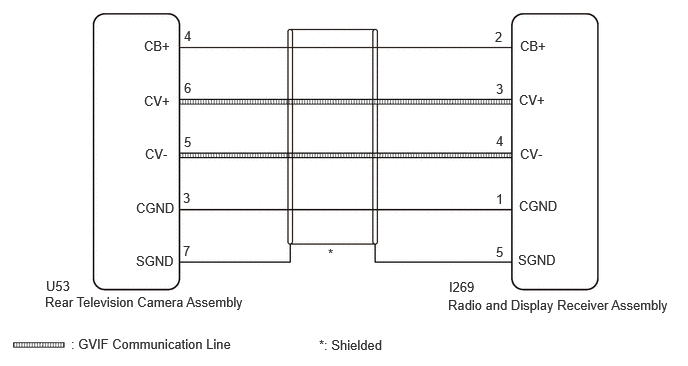
CAUTION / NOTICE / HINT
- NOTICE:
-
Depending on the parts that are replaced or operations that are performed during vehicle inspection or maintenance, calibration of other systems as well as the parking assist monitor system may be needed.
- HINT:
-
Images may be unclear even in normal conditions if:
- ·
Electrical devices are used in the cabin (noise may occur in the image).
·Accessories that generate radio waves have been installed (noise may occur in the image).
·The display of radio and display receiver assembly is cold (the image immediately after turning the ignition switch to ON may be blurred or darker than normal).
·The camera lens is dirty with snow, mud, etc.
·A strong beam of light, such as a sunbeam or headlight, hits the camera.
·It is too dark around the camera (at night, etc.).
·The ambient temperature around the camera is either too high or too low.
·The vehicle is tilted at a steep angle.
·The television camera assembly lens is scratched.
·The television camera assembly lens has drops of water on it or the humidity is high.
·When the camera is used under fluorescent lights, sodium lights, mercury lights, etc., the lights and the illuminated area may appear to flicker.
PROCEDURE
Disconnect the I269 radio and display receiver assembly connector.
Disconnect the U53 rear television camera assembly connector.
Measure the resistance according to the value(s) in the table below.
- Standard Resistance:
Tester Connection Condition Specified Condition I269-2 (CB+) - U53-4 (CB+) Always Below 1 Ω I269-3 (CV+) - U53-6 (CV+) Always Below 1 Ω I269-1 (CGND) - U53-3 (CGND) Always Below 1 Ω I269-4 (CV-) - U53-5 (CV-) Always Below 1 Ω I269-5 (SGND) - U53-7 (SGND) Always Below 1 Ω I269-2 (CB+) or U53-4 (CB+) - Body ground Always 10 kΩ or higher I269-3 (CV+) or U53-6 (CV+) - Body ground Always 10 kΩ or higher I269-1 (CGND) or U53-3 (CGND) - Body ground Always 10 kΩ or higher I269-4 (CV-) or U53-5 (CV-) - Body ground Always 10 kΩ or higher I269-5 (SGND) or U53-7 (SGND) - Body ground Always 10 kΩ or higher
- Result:
Proceed to OK NG
OK
NG
Remove the radio and display receiver assembly with its connectors still connected.
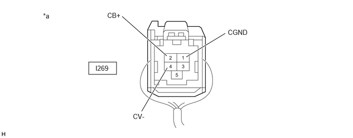
| *a | Component with harness connected
(Radio and Display Receiver Assembly) |
- | - |
Measure the resistance according to the value(s) in the table below.
- Standard Resistance:
Tester Connection Condition Specified Condition I269-4 (CV-) - Body ground Always Below 1 Ω I269-1 (CGND) - Body ground Always Below 1 Ω
Measure the voltage according to the value(s) in the table below.
- Standard Voltage:
Tester Connection Switch Condition Specified Condition I269-2 (CB+) - Body ground Ignition switch ACC 6 to 9 V Ignition switch off Below 1 V
- Result:
Proceed to OK NG
OK
NG
Remove the radio and display receiver assembly with its connectors still connected.
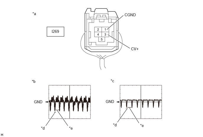
| *a | Component with harness connected
(Radio and Display Receiver Assembly) |
*b | Waveform 1 |
| *c | Waveform 2 | *d | Synchronization Signal |
| *e | Video Waveform | - | - |
Check the waveform of the rear television camera assembly using an oscilloscope.
- HINT:
- ·
A waterproof connector is used for the rear television camera assembly. Therefore, inspect the waveform at the radio and display receiver assembly with the connector connected.
·The video waveform changes according to the image sent by the rear television camera assembly.
| Item | Content |
|---|---|
| Terminal No. (Symbol) | I269-3 (CV+) - I269-1 (CGND) |
| Tool Setting | 200 mV/DIV., 50 μsec./DIV. |
| Condition | Waveform 1: Ignition switch ON, shift position in R, camera lens not covered, displaying an image
Waveform 2: Ignition switch ON, shift position in R, camera lens covered, blacking out screen |
- OK:
Waveform is as shown in the illustration.
- Result:
Proceed to OK NG
OK
NG
Replace the television camera assembly with a new or known good one.
Check if the same malfunction reoccurs when the rear view monitor screen is displayed.
- OK:
Malfunction does not reoccur (returns to normal).
- Result:
Proceed to OK NG
OK
NG